This simple circuit will produce an
alarm whenever the temperature falls below zero degree. A thermistor is
used here to sense temperature. The op-amp LM7215 is used to compare the
reference voltage and voltage from the thermistor network. Reference
voltage is given to the non inverting input (pin3) of the IC and voltage
from thermistor network is given to the inverting input (pin4).When
temperature becomes less than zero degree the voltage at the non
inverting input becomes larger than the voltage at the inverting input
and the output of the op-amp becomes high. This makes the transistor Q1
ON and drives the piezo buzzer to make the alarm. In the power supply
section, IC 7805 is used to derive 5V from the 9V battery.
Are you familiar with the
basics and applications of the 555 timer IC? Are you looking for a book
that provides all these basics? If so, CircuitsToday has started an
online store from where you can buy books on 555 timer IC, which have
been reviewed in detail. You can go through the reviews and buy them
here:- 3 Great Books to Learn 555 Timer Circuits and Projects
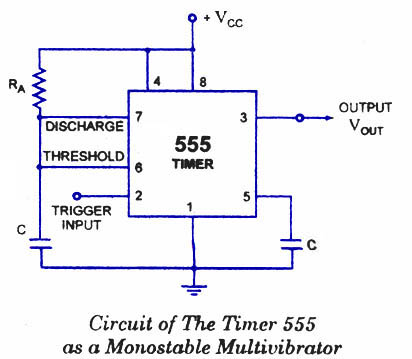
A monostable multivibrator (MMV) often called a one-shot multivibrator, is a pulse generator circuit in which the duration of the pulse is determined by the R-C network,connected externally to the 555 timer.
In such a vibrator, one state of output is stable while the other is
quasi-stable (unstable). For auto-triggering of output from quasi-stable
state to stable state energy is stored by an externally connected
capacitor C to a reference level. The time taken in storage determines
the pulse width. The transition of output from stable state to
quasi-stable state is accomplished by external triggering. The schematic of a 555 timer in monostable mode of operation is shown in figure.
The Sun's path across the sky has been known and has been predictable for a very long time. People with solar panels and solar cookers take either a high tech approach to solar tracking (light detecting electronics, etc or they manually adjust the cooker or panel. High tech is very expensive and manual adjustment is majorly error prone.
Low tech cheap tracking could improve solar performance substantially.
Low tech tracking would be valuable in really poor countrys for solar cooking and perhaps save many trees from the cooking fires.
This instructable describes my tracker that I made from an old and ugly clock.
This is a collaboration so if you have an old clock lieing around, please set it up with a gearwheel as I did and see how sturdy it is. If we can find a strong robust one, It could be bulk ordered for appropriate tech solar timing projects.
This 3V to 24 volt variable-regulated power supply can be adjusted from 3 to 25 volts and is current limited to 2 amps as shown, but may be increased to 3 amps or more by selecting a smaller current sense resistor (0.3 ohm). The 2N3055 and 2N3053 transistors should be mounted on suitable heat sinks and the current sense resistor should be rated at 3 watts or more.
Voltage regulation is controlled by 1/2 of a 1558 or 1458 op-amp. The 1458 may be substituted in the circuit below, but it is recommended the supply voltage to pin 8 be limited to 30 VDC, which can be accomplished by adding a 6.2 volt zener or 5.1 K resistor in series with pin 8. The maximum DC supply voltage for the 1458 and 1558 is 36 and 44 respectively. The power transformer should be capable of the desired current while maintaining an input voltage at least 4 volts higher than the desired output, but not exceeding the maximum supply voltage of the op-amp under minimal load conditions.
The power transformer shown is a center tapped 25.2 volt AC / 2 amp unit that will provide regulated outputs of 24 volts at 0.7 amps, 15 volts at 2 amps, or 6 volts at 3 amps. The 3 amp output is obtained using the center tap of the transformer with the switch in the 18 volt position. All components should be available at Radio Shack with the exception of the 1558 op-amp.
Most water level indicators for water tanks are based upon the number of LEDs that glow to indicate the corresponding level of water in the container. Here we present a digital version of the water level indicator. It uses a 7-segment display to show the water level in numeric form from 0 to 9.
The numeric water indicator circuit works off 5V regulated power supply. It is built around priority encoder IC 74HC147 (IC1), BCD-to-7-segment decoder IC CD4511 (IC2), 7-segment display LTS543 (DIS1) and a few discrete components.
When the water tank is empty, all the inputs of IC1 remain high. As a result, its output also remains high, making all the inputs of IC2 low. Display LTS543 at this stage shows ‘0,’ which means the tank is empty. Similarly, when the water level reaches L-1 position, the display shows ‘1,’ and when the water level reaches L-8 position, the display shows ‘8.’ Finally, when the tank is full, all the inputs of IC1 become low and its output goes low to make all the inputs of IC2 high. Display LTS543 now shows ‘9,’ which means the tank is full.
Assemble the water level indicator circuit on a general-purpose PCB and enclose in a box. Mount 7-segment LTS543 on the front panel of the box. For sensors L-1 though L-9 and ground, use corrosion free conductive-metal (stainless-steel) strips.
This simple water level indicator will activate an active buzzer (e.g. BeStar BPT-23CX ) in order to make a noise when a certain level of water is being reached. Because the water sensor and the command circuit are located on the same printed circuit board, indicator, together with its 9 V battery and the buzzer can be mounted in a compact case. Obviously the sensor, that is made by corossion, on the board, must not be mounted directly on iron or steel bathtubs but with a magnet atached on the case.
This simple fm radio receiver circuit consists of a regenerative rf stage, TR1, followed by a two of three-stage audio amplifier, TR2 to TR4. In some areas 3 stages of audio amplification may not be necessary, in which case TR3 and its associated components can be omitted and the free end of capacitor C5 connected to the collector of TR2.
Radio Receiver Circuit Diagram
The critical part of the fm radio receiver is the first stage, TR1/VC1, where the wirings must be kept as short as possible. Coil L1 is formed by winding 8 turns of 1mm (20 swg) enamelled copper wire on a 6 mm diameter former, which is then removed. After that L1 should be stretched carefully and evenly to a length of about 13mm.
Video presentation and photos of the working radio receiver
The tunning capacitor VC1 is one of the two fm sections of a miniature fm transistor radio with built-in trimmers (VC2). The “earthy” end (moving vanes and spindle) is connected to the 22pF capacitor C1. The value of the rf choke L2 is not critical, anything from 1µH to 10µH being suitable.
The output is suitable for ordinary earphones connected in series to provide an impedance of 64Ω.
Tuning-in the fm radio receiver
To operate the radio receiver, potentiometer VR1 must first be advanced slowly (towards the end of the track connected to battery positive) until, at about the half-way point, a sudden slight increase in background noise will be heard, indicating the onset of oscillation. It then should be backed off, very slowly, until oscillation just stops; it then should be possible to tune in some stations.
The correct frequency range of 87 MHz to 108 MHz can be obtained by adjusting VC2 at the high frequency (108 MHz) and slightly stretching or squeezing together the turns of coil L1 at the end (87 MHz).
Here is 10 output LED sequencer. After the last LED is illuminated, the circuit is reset. This circuit is build around readily available, low cost components - a 555 and decade counter CD4O1 7. The timer IC NE555 is wired as an astable multivibrator that produces 6Hz clock at its output pin 3. The 4017 is a CMOS decade counter with 10 outputs. Inputs include a CLOCK (Pin 1 4), a RESET (Pin 15), and a CLOCK INHIBIT (Pin 13). The clock input connects to a Schmitt trigger for pulse shaping and allows slow clock rise and fall times (not needed in our case). The counter advances one output at the rising edge of the clock signal if the CLOCK INHIBIT line is low. A high RESET signal resets the counter to the zero output. The circuit may be configured for counts less than 10 by connecting RESET to an output pin (one after the desired count). Thus, a five stage sequencer can be made by connecting pin 15 to pin 1. A CARRY-OUT signal (pin 12) can be used to clock subsequent stages in a multi-device counting chain. The output from 1C2 pin 3 is connected to clock pin (pin 14) of the IC3 for sequencing operations. NPN transistors Q1- Q10 are used to increase the output current for the LEDs which is set by the common 150 ohm resistor. In the circuit, only one of the outputs is HIGH at any one time and the output advances by one count with every clock pulse. But the circuit above is poorly designed. It does not need the voltage regulator as both chips can work up to 15v. The 4017 can supply 10mA to a LED on a 12v supply so that none of the transistors are needed. The circuit below shows the necessary components. The secret to designing a circuit is to look at the final design and ask: "is this component necessary?" Try removing a component and see if the circuit still works. Keep doing this with all the components. The circuit above was published in an Indian magazine with over 1,000,000 readers. The faults were obvious. How these faults passed an editorial committee is beyond me. They are showing very poor design-leadership in allowing this oversight to be published. The faults are technical but are obvious to anyone who has constructed the circuit and experimented with it. Obviously the circuit has never been assembled with anyone with technical expertise.
Here is a Home Alarm using 555 IC's.The Home Alarm-1 circuit above can be simplified by using a single 74C14 IC. This IC is also known by the following numbers: 40106, 40014, and 74HC14. These are CMOS chips and are characterised by low current consumption, high input impedance and a supply voltage from 5v to 15v. (Do not substitute 7414 or 74LS14. They are TTL chips and operate on 4.5v to 5.5v and have low impedance inputs.) The 74C14 contains 6 Schmitt Trigger gates and
Here is another disastrous circuit. As each output goes high it pulls the previous output high to turn on two, three, four LEDs etc. But any output that is not high is PULLED LOW by the chip and this circuit is pulling the outputs HIGH against the drivers inside the chip. This could lead to failure and certainly will heat up the chip. This circuit is a bad design and is not recommended.
In the following circuit an LED is used to give a fixed reference voltage to a transistor. The output constant current I out is given by: The LED lights up only when a load is connected at the output. Thus it indicates when the circuit is operating.
The operation of the circuit can be made clearer by re-arranging the components as follows:
The output will be limited to 100mA by using a red LED and 10R for Re. The output will be limited to 500mA by using a red LED and 2R2 for Re. The output will be limited to 1A by using a red LED and 1R0 for Re.
This instructable will show you how to make your own solar battery charger from very simple components. It is taken from my documentation provided with a kit I supply - you should easily be able to source the same components yourself of course.
If you have any comments on how to improve the documentation then please do not hesitate to say :)
The items shown in the image are contained in your kit. This page explains their uses. Your kit may have a smaller/larger copper stripboard than this and may contain extra wire - I try to beef up the kit as time goes on.
The Copper Stripboard contains rows of copper tracks. Each track is electrically separate from its neighbour. It contains holes for your components. The boards I supply are larger than needed, this will allow you to expand the system at some future date.
The Batter Holder ... errrr holds your batteries.... and comes with two pins, one for the positive and one for the negative ends, they will be soldered into the stripboard.
100 Ohm resister - at one point this was needful in the kit as the LED couldn't cope with some of the voltages in the experiments - however the new LEDs do and the resistor is simply in there because it is advertised as such! Maybe you will have need of it when you expand the system.
LED - this is a high intensity light emitting diode. 3.2-3.6V forward voltage, with 10000mcd at
Too hot or too cold? Make it just right (and make Goldilocks proud) by building this dual-purpose device.
Down here in Arizona, we've got some pretty hot summers, at around 120 degrees. And inside, it gets up to about 88, which is a bit hot for my taste, especially when I've got my computer on- then it's even worse.
Or, if you live somewhere cold and wish your room was warmer at night, just flip a switch and your wish will be granted with this air cooling and heating machine.
And it's cool looking too!
Step 1: Materials
Oh man. This project requires a bunch of stuff, but you probably have most of them lying around from old broken things.
You do keep old things you don't use any more in a parts closet, right? Good.
-2 80mm computer case fans: I used one of a normal thickness and one half-sized one with more blades. You'll see why later.
-A transformer: I got mine from an old speaker set that I converted to run on batteries. It steps
in 2011 I built a Tear drop trailer (TD) similar to this http://www.instructables.com/id/Teardrop-Travel-Trailer/ , most TD campers carry some sort of air conditioner to deal with the hot weather. In dry areas of the country a swamp cooler works fine as blowing a fan over a block of ice will cool the air and any moisture picked up from the ice will feel nice.
In humid areas of the country a swamp cooler just adds to the misery, I remember spending a few weeks in Mena, AR at a paint shop. At 97 F and 90% humidity the sanding crew was dying from the heat in the shade, so the boss went out and borrowed or rented a swamp cooler. As I was just observing our aircraft being painted I could sit right in front of the swamp cooler all day, from walking around I discovered that the cooler feeling air only lasted about 4-6 feet from the cooler, after that the breeze felt ok and more than 10 feet away all you got was the noise of the huge fan.
The swamp cooler was about 6 feet square, it had a 5 foot tall fan blowing through some sort of paper strips that were being saturated with water being pumped over them from a large tank in the base. the base tank needed to be hooked to a garden hose to keep it from going dry. For all the water being evaporated I think the swamp cooler just made it worse inside the paint shop, and it made the paint jobs have problems.
the main reason air conditioning feels so nice in humid areas is that the air conditioner removes quite a bit of water vapor, dry air allows you to sweat, which is the way your skin gets rid of extra heat. Just look underneath your car or air conditioner and you will see a puddle on a hot humid day. In fact modern cars run the air conditioner on low when you select "defrost" to remove the excess moisture.
For those of us who don't want to lug an air conditioner in our trailers (or tents), and where a swamp cooler won't work, or where you would need a 50 mile extension cord or deal with a generator, I took a few different ideas from Instructables.com and put them together in my car.
Being from Maine, I bought a new car without air conditioning, since we only need AC for a week or two up here almost 25% of cars are sold without AC, saving about $800. Since then I got a job in central NH where the weather is much hotter than coastal Maine. I decided I needed some AC.
I bought a used heater core off of fleabay for $25, a cooler that would fit between my kids booster seats in the back seat $35, two computer cooling fans for $15 fleabay, and a 12 volt live bait well pump $30 wallyworld boating isle. When assembled as shown the heater core blew cold air on the back of my head, but was not enough to cool off my car with it's untinted windows and blazing sun shinning in. I also thought my heater core was garbage as water streamed from it while it was running, after pressure checking it I found it was still good, I had been condensing tons of water out of the humid air.
While this was a failure, I learned a few things, that if applied to a well insulated area (inside my TD which if you made it a cube would only be 160 cubic feet (5' W X 8' L X 4' H)) will work as long as enough ice is used.
I modified my "air conditioner" into a "body cooler" and now it works great, and the ice lasts forever.
Step 1: what are you hacking together?
to build a 12 volt air conditioner or body cooler you will need mostly the same items..
-flexible hose and clamps
-12 volt bait well pump (I bought the 500 gph model, way over kill on the flow rate but cheap)
-wiring
-cigar lighter plug
-largest cooler you can fit in the area it will sit. (air conditioners are rated in BTU's, the smallest ones for sale cheap are the 5,000 BTU ones, house and larger ones are rated in tons, this air conditioner will depend on how much ice you can put in it) I found the "marine" coolers the best for what I needed as they tend to be all white (less solar heat gain) and much more rectangular with less bulk (takes up space) mine also has large easy to hold handles (easy to strap into the seat belt in the car, and easy to carry full of ice and water) it also has an external hinge, most hinged lid designs have a air leak around the hinge, the external hinge type have a lid that will lock in place even if you remove the hinges.
-zip ties
for a 12 volt air conditioner you will also need:
-a car heater core (mine was from a jeep Cherokee, I figured one from an SUV or van would have a larger heat exchanging area than one for a small car)
-as many 12 volt fans as it will take to cover the grid section of the heater core.
-12 volt switches or a house thermostat (if you want the fan to go on and off at a certain temp)
-a drip pan that is larger than the heater core and some sort of drain line to carry condensation back to the cooler
for a body cooler:
-small diameter PEX plumbing and fittings (I used 3/8" but now I see 1/4" in some hardware stores)
Tools:
drill and hole drills
screw drivers
wire crimpers
pex ring crimpers (if you use pex) (my crimper is a two part C shaped set of jaws that you squeeze using vice grips, it has spots in it to crimp 3/8", 1/2", 3/4", and 1" pex copper crimp rings.
Step 2: making your heatsink
just like dark is the absence of light, cold is the absence of heat.
- Remove the hinges from the cooler lid, mine came off with screws so it was easy. You want the pump, wiring, and return tube, all connected to the lid so it can be left in place while you go fill the cooler with ice and water.
-Put the 12 volt pump in one corner of the cooler, if the cooler will be sitting on a seat or other tilted area put the pump at the lowest end.
-connect the flexible tubing to the outlet nipple of the pump and secure it as needed (the pump I have has the nipple coming out the side, I used clear plastic tubing to connect on to the nipple, and then a plastic pex 90 degree elbow to run my tubing vertically up to the cooler lid.
-mark the lid of the cooler where you want to run your tubing through it.
-drill the smallest hole you can get the tubing through to minimize air leaks.
-drill another hole in the lid, right next to the first one, or at the opposite end, it is more convenient for me to have both hoses next to each other, however to make sure the water is going through all of the ice I added a 90 degree elbow to the hose to shoot the water at the opposite end of the cooler from the pump.
-seal the holes in the cooler lid with RTV
Step 3: cooling off a tear drop trailer
-install the heater core where you want it, I plan on having mine installed near the top of the galley wall in the galley, with a vent into the TD sleeping compartment.
-mount your 12 volt fans so they blow through the heater core. I plan on one fan bringing in outside air all the time, and the other recirculating air from inside the TD.
-mount a drip pan underneath the heater core with a drain line back to the cooler.
-run the wires from your 12 volt power source to a switch or two. I plan on having my TD have two fans both running continuously, one bringing in fresh air the other recirculating TD bedroom air, and a wall thermostat switching the 12 volt pump on and off. This may exceed the amps rating for a normal wall thermostat but they also sell 120/220 V wall thermostats that will work.
-run the plumbing from the heater core to the cooler and clamp the ends if needed.
-zip tie everything in place as needed.
-fill the cooler with ice or ice packs, I use juice bottles full of water (fill 3/4 full, dump in salt and shake until the water won't absorb any more, put the lid on and freeze with the bottle on its side) leave a space for the pump (I plan on making some sort of baffle to keep ice away from the pump )
-put in enough water to cover the top of the pump.
-put the the cooler back together, turn it on, check for leaks.
-enjoy hours of cool air in your TD.
since a TD is mostly used inside for sleeping, a cooler full of ice should last the night, however you will probably have to refill the ice and dump out most of the water from the night before. Since most campgrounds, and gas stations have ice for sale this shouldn't be too hard.
I have posted this idea on tnttt.com and one guy has tried it, http://www.tnttt.com/viewtopic.php?f=29&t=18104&hilit=rowerwet&start=15 the guy who tried it is near the bottom of page 2 of the thread
his quote " I used 10lbs of ice and it lasted about 5 hours at 88 degree's outside, my Tear maintained 76 degrees." He goes on to give ideas on how he wants to improve the design using a copper coil inside the cooler instead of a large bath of water, to do that though would require some sort of reservoir for expansion of the water, not hard, just a little more details, is all.
just like my other I'ble on how to heat a TD or tent off the grid, this gives a way to cool a TD off the grid. In fact ice was around a long time before refrigerators, my parents house is built in the area that an ice house once stood hundreds of years ago. During the New England winter ice was cut out of the pond behind their house and packed in straw and saw dust in double walled ice barns, the ice was even shipped all around the world in old sailing ships packed in straw and sawdust to be sold.
this is my current design instead of air conditioning in my car, it is a direct copy of this I'ble http://www.instructables.com/id/Too-Hot-Remove-heat-from-your-body-with-the-Back-/ only mine uses pex as the heat exchanger, this works very well, almost too well, I have had to unplug it more than once while driving on very hot days, as I found I wasn't sweating anymore and was starting to feel a little sick to the stomach. a timer circuit or some sort of clip on body thermostat might be a good idea.
IF YOU HAVE CIRCULATION PROBLEMS THIS IS NOT A GOOD IDEA FOR YOU! IT WORKS TOO WELL AND COULD KILL OR BADLY HURT YOU.
After my heater core Air conditioner idea failed due to the heat coming in through the window glass, I took the heater core off of the cooler and made a back heat exchanger this way:
-measure the length of the nipples on the T fittings with the tips touching,
-cut a short piece of PEX to cover that length and install it on the nipples with a PEX lock ring.
-crimp the ring in place with the pex crimper.
-continue the string of T fittings with all of the T lower legs pointing up until you reach the width of the seat back it will be installed on.
-for the last pipe you need a 90 degree fitting instead of a T fitting.
-count the number of T's and put another string together that matches the first string you made
-measure the height of the seat back and cut the small diameter PEX tubing to length
-install the PEX tubing to the T legs to connect the upper and lower runs, with the exit for the water at the top opposite the in for the water at the bottom.
-I used two 90 degree PEX fittings at the top to turn the water return 180 degrees behind the headrest of the car seat to lock it in place.
-connect the lower and upper supply/return lines to the flexible tubing coming from the cooler
-run the wires from the cigar lighter plug to the pump. an inline switch might be nice as it would save plugging and unplugging the cigar lighter every time. my cigar lighter plug has an LED in it to let me know it is getting power. The first time I used it I bumped the cord and the fuse inside the plug blew, since I knew my cell phone charger still worked that meant the plug had the open, which turned out to be the fuse.
-fill the cooler with ice and just enough water to cover the pump
-put the pump in the cooler so it is at the back in most cars, as the seat slopes toward the back.
-this design is so efficient that you could easily us a very small cooler, or do all of the seats in the car, and since the pump is rated for 500 gph it would handle all four, just install a simple in line ball valve for each seat back to regulate flow if no one is sitting there.
this set up works great and you really don't notice the pipes as the seat back lets them sink in.
-I like having clear plastic supply lines also as they let me see that water is flowing, however they are not rigid enough to keep from being collapsed by my weight against the seat back, PEX is very rigid, I could probably stand on a PEX pipe, and even if it did collapse it would just snap back.
running the water from the bottom of the seat back to the top ensures that it is always full, if it ran from the top down the water could drain through the first few tubes and leave the last few empty