Showing posts with label led. Show all posts

Wednesday, January 20, 2016

Puff to OFF LED circuit

Descrption.
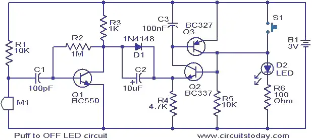
Image titled Make a Small Heater Step 1This is a simple circuit in which the glowing LED can be switched OFF just by a puff. A condenser mic (M1) is used to sense your puff. When the push button S1 is pressed, the transistors Q2 and Q3 wired as latching pair gets activated and drives the LED to glow. The LED remains in this condition. When you puff on the condenser mic, the sound pressure is converted into a voltage signal at its output. This voltage signal will be amplified by the transistor Q1.Since the collector of the Q1 is coupled to the emitter of the latching pair, the pair will stop conducting when ever there is a signal from the condenser mic due to puffing and the LED will go OFF.  The push button switch S1 has to be pressed again to switch the LED ON.
Circuit diagram with Parts list.
puff-top-off-led.JPG
Notes.
  • The circuit can be powered from a 3V battery.
  • The M1 can be a general purpose condenser microphone.
  • The switch S1 can be push button switch.
  • The circuit can be assembled on a good quality PCB or common board.
  • Instead of the LED, you can also try a low power 3V bulb.

Water level Controller

Image titled Make a Small Heater Step 1 Water level controller circuit

Note:- We have developed another water level controller circuit using micro controller AT89S51 from Atmel. If you are interested, read that too :- Water level controller using micro controller
Are you familiar with the basics and the different applications of the 555 timer IC. If not, we recommend you 3 books that provide a very good understanding of the IC and its applications. You can check out the reviews and buy the book from our online store:- 3 Great Books to Learn 555 Timer Circuits and Projects.
Description.
A simple but very reliable and effective water level controller circuit diagram is shown here. The circuit uses 6 transistors, 1 NE555 timer IC, a relay and few passive components. The circuit is completely automatic which starts the pump motor when the water level in the over head tank goes below a preset level and switches OFF the pump when the water level in the over head tank goes above the full level.
Probe D is positioned at the bottom level of the tank while probes A, B and C are placed at full, half and medium levels of the tank respectively. The level sensing part of the circuit is built around transistors Q1, Q2 and Q3. When water level is below the quarter level probes A, B and C are open and the transistor Q1, Q2 and Q3 remains OFF. When the water level rises and touches the probes the corresponding transistors gets biased and switches ON. Resistors R1, R2, R3 limit the bases current of corresponding transistors while resistors R4, R5, R6 limit their collector current. LEDs D1, D2 and D3 provide a visible indication of the current water level.

Tuesday, November 10, 2015

Numeric Water Level Indicator Circuit

Most water level indicators for water tanks are based upon the number of LEDs that glow to indicate the corresponding level of water in the container. Here we present a digital version of the water level indicator. It uses a 7-segment display to show the water level in numeric form from 0 to 9.

The numeric water indicator circuit works off 5V regulated power supply. It is built around priority encoder IC 74HC147 (IC1), BCD-to-7-segment decoder IC CD4511 (IC2), 7-segment display LTS543 (DIS1) and a few discrete components.
When the water tank is empty, all the inputs of IC1 remain high. As a result, its output also remains high, making all the inputs of IC2 low. Display LTS543 at this stage shows ‘0,’ which means the tank is empty. Similarly, when the water level reaches L-1 position, the display shows ‘1,’ and when the water level reaches L-8 position, the display shows ‘8.’ Finally, when the tank is full, all the inputs of IC1 become low and its output goes low to make all the inputs of IC2 high. Display LTS543 now shows ‘9,’ which means the tank is full.

Water Level Indicator Circuit Schematic

numeric water level indicator circuit diagram
Assemble the water level indicator circuit on a general-purpose PCB and enclose in a box. Mount 7-segment LTS543 on the front panel of the box. For sensors L-1 though L-9 and ground, use corrosion free conductive-metal (stainless-steel) strips.
Source:-http://www.electroschematics.com/5655/numeric-water-level-indicator/

Water Level Indicator Circuit

This simple water level indicator will activate an active buzzer (e.g. BeStar BPT-23CX ) in order to make a noise when a certain level of water is being reached. Because the water sensor and the command circuit are located on the same printed circuit board, indicator, together with its 9 V battery and the buzzer can be mounted in a compact case. Obviously the sensor, that is made by corossion, on the board, must not be mounted directly on iron or steel bathtubs but with a magnet atached on the case.

Schematic of the Water Level Indicator Circuit

water level indicator circuit


Check out the new water level sensor circuit.
In order to

10 OUTPUT LED SEQUENCER


Here is 10 output LED sequencer. After the last LED is illuminated, the circuit is reset. This circuit is build around readily available, low cost components - a 555 and decade counter CD4O1 7. The timer IC NE555 is wired as an astable multivibrator that produces 6Hz clock at its output pin 3. The 4017 is a CMOS decade counter with 10 outputs. Inputs include a CLOCK (Pin 1 4), a RESET (Pin 15), and a CLOCK INHIBIT (Pin 13). The clock input connects to a Schmitt trigger for pulse shaping and allows slow clock rise and fall times (not needed in our case).
The counter advances one output at the rising edge of the clock signal if the CLOCK INHIBIT line is low. A high RESET signal resets the counter to the zero output. The circuit may be configured for counts less than 10 by connecting RESET to an output pin (one after the desired count). Thus, a five stage sequencer can be made by connecting pin 15 to pin 1. A CARRY-OUT signal (pin 12) can be used to clock subsequent stages in a multi-device counting chain.
The output from 1C2 pin 3 is connected to clock pin (pin 14) of the IC3 for sequencing operations. NPN transistors Q1- Q10 are used to increase the output current for the LEDs which is set by the common 150 ohm resistor. In the circuit, only one of the outputs is HIGH at any one time and the output advances by one count with every clock pulse.

But the circuit above is poorly designed.
It does not need the voltage regulator as both chips can work up to 15v.
The 4017 can supply 10mA to a LED on a 12v supply so that none of the transistors are needed.
The circuit below shows the necessary components.
The secret to designing a circuit is to look at the final design and ask: "is this component necessary?"
Try removing a component and see if the circuit still works. Keep doing this with all the components. The circuit above was published in an Indian magazine with over 1,000,000 readers. The faults were obvious. How these faults passed an editorial committee is beyond me.  They are showing very poor design-leadership in allowing this oversight to be published. The faults are technical but are obvious to anyone who has constructed the circuit and experimented with it. Obviously the circuit has never been assembled with anyone with technical expertise.

MOVING LEDs


Here is another disastrous circuit. As each output goes high it pulls the previous output high to turn on two, three, four LEDs etc.
But any output that is not high is PULLED LOW by the chip and this circuit is pulling the outputs HIGH against the drivers inside the chip. This could lead to failure and certainly will heat up the chip.
This circuit is a bad design and is not recommended. 

LIGHT CONTROLLED LAMP

Here is a circuit of light controlled lamp. This is basically a Schmitt Trigger which receives input from a cadmium sulfide photo cell and controls a relay that can be used to switch a lamp on and off at dawn and dusk. The photo cell should be shielded from the lamp to prevent feedback so the lamp light does not strike the photo cell and switch off the lamp.
The photo cell is wired in series with a potentiometer VR1, so the voltage at the base of transistor Q1 can be adjusted to about half the supply, at the desired ambient light level. The two PNP transistors are connected with a common emitter resistor to produce a gap between the on and off voltages - called the HYSTERESIS GAP.
Under dark conditions, the photo cell resistance will be high producing a voltage on the base of Q1 that is higher than the base voltage on Q2. This causes Q2 to conduct and activate the relay.
The switching points are about 8 volts and 4 volts using the resistor values shown but could be brought closer together by using a lower value for R3. A value of 3k3 would move the levels to about 3.5v and 5.5v. 

EMERGENCY LIGHT

Here is a circuit of an emergency light. As long as the power supply is present, transistor Q1 conducts. Since the base of the transistor Q2 is connected to the collector of Q1, transistor Q2 and Q3 do not conduct and hence the lamp remains off. LED glows as long as the supply is present.
When the power supply fails, the base drive to Q1 disappears. Thus Q1 stops conducting and its collector voltage jumps to battery voltage and starts conducting, switching on the lamp instantly. The load current is supplied by the battery. Whenever the power supply is restored, Q1 starts conducting turning Q2 & Q3 off and the lamp is switched off. Transistor Q2 conducts and provides sufficient base drive to transistor Q3.

The circuit above is too complex. The first diode is not needed and the rest of the circuit can be re-arranged. 
The 2R2 will overcharge the battery and dry it out in a few months.
It can be simplified to this:

The 100R gives 40mA charging with a 12v battery and 12v DC plug pack.

16-LED NIGHT RIDER


The bi-directional sequencer uses a 4 bit binary up/down counter (CD4516) and two “1 of 8 line decoders" (74HC138 or 74HCT138) to generate the popular Night Rider display. A Schmitt Trigger oscillator provides the clock signal for the counter and the rate can be adjusted with the 500k pot. Two additional Schmitt Trigger 
inverters are used as a SET/RESET latch to control the counting direction (up or down). Be sure to use the 74HC14 and not the 74HCT14, the 74HCT14 may not work due to the low TTL input trigger level. When the highest count is reached (1111) the low output at pin 7 sets the latch so that the UP/DOWN input to the counter goes low and causes the counter to begin decrementing. When the lowest count is reached (0000) the latch is reset (high) so that the counter will begin incrementing on the next rising clock edge. The three lowest counter bits (Q0, Q1, Q2) are connected to both decoders in parallel and the highest bit Q3 is used to select the appropriate decoder.

Monday, November 09, 2015

Thermoelectric Rotational Ornament

Picture of Thermoelectric Rotational Ornament
DSC00315.jpg
DSC00316.jpg
DSC00287.jpg

VIDEOS


Background:
This is another thermoelectric experiment/ornament where the whole construction (candle, hot side, module and cool side) is rotating and both heating and cooling itself with a perfect balance between module output power, motor torque & rpm, candle efficiency, heat transfer, cooling efficiency, air flow and friction. A lot of physics are going on here but with a very simple construction. I hope you enjoy this project!
See videos for final result:

Instrument controlled by brightness of light!

Create a functional circuit diagram that makes an instrument controlled by brightness of light!

This is one of the 48 projects for our Instructables: Made In Your Mind (IMIYM)exhibition at the Children’s Museum of Houston showing from May 26, 2012 - November 4, 2012. Produced in partnership with Instructables, IMIYM is an exhibit where families work together to build different fun, toy-like projects that help construct knowledge and skills related to science, technology, engineering, and mathematics while instilling a “do-it-yourself” attitude in kids so they feel empowered to explore, tinker, and try to
make things themselves. To learn more, check out the article here.

For this project, we were inspired by the How to Make an Easy PhototheraminInstructable created by TigrisLi (which, as I discovered is based on the Audible Light Probe by Forrest M. Mims III of Radio Shack books fame) , but there may be others on Instructables that are also similar. Often, the materials and process for building our projects are designed for use with a large number of visitors (we see over 800,000 annually) and the need to ensure safety in a mostly non-facilitated environment (in other words, no soldering). So, yes, many of these projects have room for improvement in both materials and methodology, which is PRECISELY what we want to encourage the kids to do. So please do share your ideas for improvement and

Electric Generator Powering LEDs

Picture of Electric Generator Powering LEDs
Introduction
The Electric Generator is designed to help students understand how electricity is generated by actually allowing them to generate their own electricity. This generator is created using mostly household items. Follow the instructions below for optimal power generation. Have fun!

Video:


Materials List

CardboardMagnet Wire
Metal Rod2x Magnet
StringRed LED (1.6v)
Optional Green (2.2v) and Blue (3.8v) LED


Suggested Tools:
  • Hot Glue Gun
  • Scissors
  • Sandpaper
  • Multi-Meter
  • Wire Stripper
  • Ruler
  • Electrical Tape

Sunday, November 08, 2015

Dark Sensor with LDR, transistor and a LED

You wan't do a dark sensor with a LDR, one transistor and one LED and you don't know how to do it? In this small tutorial I will explain to you how you can do that even if you know only the basics of electronic.

Parts you need:

1 Breadboard;
1 Power source of 12v;
1 Transistor (in this case we use the BC547);
1 Resistor of 1KOhm;
1 Resistor of 680KOhm;
1 LED (in this case blue);
1 LDR:
Some condutor cables to connect the parts.

Step 1: Connecting parts in the breadboard

Picture of Connecting parts in the breadboard
In the above image we can see the circuit we will construct. It's a simple electronic circuit and if you know how to do something on a breadboard, you should be able to do that dark sensor.


Night light with ldr

Picture of Night light with ldr
temp_858870445.jpg
temp_457891152.jpg
temp_-891094811.jpg
with ldr

Step 1: Things Needed

1. Transistor (2N3906)
2. leds
3.resistor (brown-black-orange-gold)
4.LDR
5. Another resistor for saving the led from burning out(red-red-brown-gold)
6.some hookup wires for connecting
the parts together
7. Breadboard

EL wire color organ

Have you ever used EL wire, or felt that it'd be nice to have a wire that lights up, instead of expensive LED strings?  How about some that pulse with music?  That's what this is for, the EL wire color organ.  EL wire is composed of three wires.  One big center wire surrounded by a phosporous coating.  Two smaller wires are wrapped around it, and connected at the end of the wire.  One end is left open, the other connected to the power supply.  When about 120VAC at a few kHz is run through it, the phosphorous glows.  This is a problem for traditional color organs, as they use either low voltage DC for LEDs, or low frequency AC for incandescent lights.  This project accomplishes the music reaction, high frequency, and high voltage issues with a small device.  I used it for a tron-style holloween costume that reacts to music.

Music LED Light Box

Picture of Music LED Light Box
My original LED light cube got allot of reactions. Some of them where about making the LED's react to music. This did sound very interesting and I found some instructables on here.
Unfortunately I found it very hard to understand those instructables. In my opinion they weren't explained well enough and even some circuits weren't correct.

That's why I though I build one and make an instructable of it. I tried to make this instructable so easy, that everyone with or without any experience can make one!

If you make one, don't forget to share your end result photos and movies with us.

Below you'll see the end result of my Music LED Light Box.

The movie is shot with my Canon Digital Camera, in the dark. My camera can't handle the fast switching between light and dark very well. In reality the effect is even nicer then on the video.


Before people go asking who's music or what songs these are in this video, these beats are made by my brother.  :)
You can visit his website www.motabeatz.com or  YouTube channel for more information and songs.

Water Level Indicator with Alarm

Picture of Water Level Indicator with Alarm
Introduction
Today I am going to talk about a very useful project that I had taken up. It is called the Water Level Indicator. Nowadays everybody has overhead tank at their homes. But everyone who has a water tank above knows the kind of problems that they face. Firstly there is no system to track the water in the tank. Then there come a secondary problem that is when their water pump is started they have no idea when it gets filled up and sometimes there are situation where the pump keeps onpumping water to the tank and the water starts spilling out from the tank. There iswastage of energy as well as wastage of water.

Later History
This project that i had taken up is the result of  long hours of research of work at the Internet as well as long hours of thinking. I had made various versions of the projects earlier but at last i came up with this final product. I bet this has been tested and i can now firmly say that the model would work flawlessly without any complains for years. I am saying this as i have installed this models to various houses in my neighborhood and all are working fine without any maintenance. And indeed this model is admired by all who uses it.

The Situation 
The house where I live in has an overhead tank which is about 30 feet from the ground level. I was getting bored going up the rooftop to check whether the tank has filled or the water level was below to start the pump. I had to do this again and again. Then I sought for a solution. I always used to think of the possibilities of how can this problem be tackled in an electronic way. After years of research and by trial and error,  I found one and wanted to put whatever I have done out here so that it may be helpful to someone who has a overhead water tank at their homes.

Step 1: The Working Principle

Basically the unit is made up of various sensors acting as a switch. Let me explain in a simple way. What happens is when you turn on you water pump, the water starts to get pumped from your underground reservoir  or from your underground water supply from the pipes to your water tank. In the tank there is a set of sensors( to be precise there are 7 sensors), in the water tank. Just think them as a switch, as the work of the sensor will be to connect a circuit. I will explain in details in my instructables. So the water starts to get filled in the tank and when the water level in the tank starts to rise up, what happens is that the sensors that is installed in the tank starts to get activated one by one indicating the water level in the tank. And finally when it reaches to its top most sensor, there will be a visual display as well as a sound from the unit indicating that the water has filled in the tank and one can be alerted that the tank has been filled up and the water pump has to be switched off saving the electricity bill as well as over flow of water from the tank.

There are Four parts in this project:-

(i) The Sensor Part

It is generally a fixed support inside the tank having some nuts and bolt with wires coming out.
(ii) The Circuit Part
It comprises the brain of the module, where in all the various inputs from the sensors are fed. It is the unit from where you will get all the information of how much of water is in the tank.
(iii) The Power Supply 
It is the part where in you will be converting the A/C voltage to a regulated voltage of 5V to the Circuit.
(IV) The Buzzer Part
It is responsible for bringing up the sound when the water level fills up in the tank. It will also be having a speaker or a buzzer to alert.

Step 2: The Circuit

It has numerous transistors acting as a switch and the switch gets activated when the sensors tell them to.

The heart of the circuit is the transistors BC 547. There are total 7 transistors in the circuit and each one will be sensing the level of water present in the overhead water tank. There is one extra power LED without a transistor and that is because this Red LED will be telling us two things. Firstly when you power the unit it will be monitoring the power present in the unit and secondly it is also the indicator telling you that there is no water at all present in the tank. As because the water level is below the No. 1 (as shown in the circuit) sensor, no LED's will be lighting up, but only for the one Red LED. Therefore when you switch on your unit if you see only one Red LED lighting up then you know that the is no water present in the tank and therefore you should make you water pump on.
Then as shown in the figure i have given all the LED's in various color. Starting from the beginning is
  1. Red LED (Indicating no water in the tank as none of the sensors are getting contact with the water)
  2. Red LED ( Level 1, indication very low water in the tank )
  3. Yellow LED (Level 2, indication of low water)
  4. Yellow LED (Level 3, indication of 1/4 of water in the tank)
  5. Green LED (Level 4, indication of half of water in the tank)
  6. Green LED (Level 5, indication of more than half of water)
  7. Green LED (Level 6, indication of nearing filling up the tank)
  8. Blue LED (Level 7, Full indication of tank and buzzer comes on)
Now as the water starts to rise up the sensors starts to get in contact with the water and the transistors are activated and there is a flow of current in the transistors making the LED's light up. Here in between the transistor and the LED there is a current limiting resistor 470 ohms, the job of the resistor is to checks that the LED does not get over voltage and destroy the LED. The transistor is biased by a 470K resistor with the ground and the sensing part is taken from the collector with a 33 ohms resistor going directly to the tank. As i have shown in the diagram the signals are drawn in the Green color. There by you can follow the LED's as they light up from Red to Yellow and then Green and finally to Blue making a sound.

The Buzzer Part
Here you can add any of the normal buzzers that are readily available in the market and if  it is not then you can make yourself with a simple 555 IC. I am giving a small circuit diagram, it is really simple to make and there are minimum parts. It is a simple audio oscillator. I have also provide a circuit diagram here but if you are able to manage a buzzer then no need to assemble this circuit.

The Power Supply
This section contains a transformer converting the mains voltage 220V bring down to 9V. There is a bridge rectifier containing 4 diodes and making the Alternating current to Direct Current. After the filtering the voltage is then directly fed to the voltage regulator (7805) with a filtering capacitor. From the regulator IC the output voltage is then again filtered with a capacitor and is fed to the circuit. This comprises the power supply of the device.

This completes the electronic part of the project and now i will be going to the sensor part, which is also made easily.

Step 3: Putting the circuit in a box

Now time to put the compiled circuit in a small box. Here i chose a Junction boxthat are used in electrical wiring. It was a perfect box for this project.
Now the tricky part is making holes in the plastic junction box so that LED can easily slip through the holes, also the spacing between the LED's should be proportionate. First take the box and draw the outline in the face of the box. First for the switch you should make a marking at the bottom right hand side. Then mark the points for the LED's. As told earlier it should be proportionate. Now unbend a paper clip and heat it with a soldering iron and make holes to the marked points as shown in the figure.

Then cut the plastic board for the power switch. After the cut is made file at the edges so that the cut is smooth and the switch can easily fit to into the cut. Fit in the Power Switch. 

Time for adding the LED's to the panel. Let's start by adding the Red LED from the bottom end. Then to the Yellow and Green and finally Blue. This LED's should be then be soldered to the PCB as shown in the circuit diagram. For me what i did was soldered directly to the PCB below the front panel, as it gave a solid base for the LED's.

Now fix the buzzer just beside the PCB and give the connection from the circuit board. Then also fix the Power supply at the box with the help of nuts holding the transformer firmly to the box.

For making a junction of the sensors you can use a cable connector, i used from a used TV circuit board as shown. This connector was actually connecting some wires with the television PCB to the CRT(Cathod Ray Tube of the TV), therefore i decided to use this as it had many pins. I then cut it from the PCB and numbered it from 1 going up till 8. You will notice that there were two pins extra, so i made this two pins connect together and made a common point for the sensor going to the tank. The rest of the pins starting from Pin 1 going up till 7 will be for the sensing part which will also be connected to the sensors of the water tank.

The Nos. that i have assigned for the sensors are as follows:-

1: (Level 1) water is considerably low and pump needs to be started
2: (Level 2) water is low
3: (Level 3) Water level is 1/
4: (Level 4) Water level is Half
5: Level 5) Water level is more than half
6: (Level 6) Water level is about to fill up
7: (Level 7) Water level has filled up and alarm starts to sound
8: Common Positive Pin 

Therefore there are in total 8 supply line that has to be taken out from the main circuit board to the sensor. After trial and error, and a few failed experiments i found out that the best wire to be used in the project would be a Cat5 cable as it has also in total 4 pairs of wires and this can be blended in this project nicely. As it would be virtually impossible to buy lots of wire and then take it to the tank. It would be messy and there would be all short of wiring problem.
And one advantage in adding a  junction, while installation is that there won't be any problem for soldering the wires to the circuit while installation. It would be just plug and play. Therefore after the wire is connected to the connector. I hot glued it as it would keep the wires firmly fixed to the female connector,and there won't be any dis-connection.

My rented house that i live is about 3 stories high and i needed approximately 15 meters of CAT5 Cable.

That end's this part of connecting the cable with the circuit and the next part will be learning to make the sensors for the water tank.

Step 4: The Sensor Part

This is the easiest part of the project to build. You only have to make two conductors so that when it is in contact with water it will act as a switch, as water is a good conductor of electricity.

Lets start with finding a plastic PVC pipe or you may use any short of plastic wire casing. In my part what i did was make it with wire casing, that are utilized while wiring at houses, but if in case you don't have you can make it with a PVC pipe.
Then your next step is to measure the height of the tank that is from bottom till the neck and accordingly cut the PVC wire casing. Then mark points 1 to 7 leaving some spaces as desired. For example you can measure the whole length and divide it by seven, as because you have to mark seven different points for sensing seven different water level.

Example:-
Your tank height from bottom to top is 6 Foot (182.88 centimeter),
You divide 182.88 centimeter by seven then you get
182.88 / 7 = 26.12 cm
Therefore you have to mark points at intervals of 26.12 cm.

After marking the different water level in the PVC wire casing, find some 3 inch nut bolts as shown in figure. Drill the holes to the points marked keeping the size of the diameter of the nuts, It should snugly fit to the wire casing. Then as when the nut is fitted to the casing, don't bolt the nut as such. Make a wire loop as shown and then solder it's outside part so that it can slip to the nut easily.
The length of the wire should be kept long (i.e more than 6 foot for the first sensor)and the length of the second sensor would be short then the first sensor, so this should be continued till you have 7 wires with 7 loops with varying lengths.

Now put the loops of wire to the nuts that you have snuggled to the plastic wire biting and make the wires come out from every nut that you have built. After all the wires are fixed to the nut, you should now add a common line to the wire casing. For the common line you can use a naked wire running through the nut bolts bare touching each other. The gap of the naked wire and the bolt should be kept minimum and if you want you can solder a small piece of wire to the common line just beside the nut and bolt as the sensing would be more. when the water comes in contact with the common wire and the bolt, there will be transfer of current from the naked wire to the bolt and the sensing is done.

After connecting all the wires to the bolt there will be a mess of wire hanging from the wire casing, what i did was hot glued all the wires in a line wise fashion so that the wires don't fall out of place. All the wires were then junctioned to a PCB board from which the sensing part would be taken out. This is shown in the figure. Therefore this completes our sensor also.

Now for the final part where i will be talking about the Installation.

Step 5: Installing the Device

The final part is installing the device to the tank and make it working.

First start with installing the water sensor in the overhead tank. As in figure this is the tank that we are going to install the sensor. Just survey the tank from every side to see that you can fit the sensing part. Now take the sensor rod that you have prepared and dip into the tank so that it just touches the bottom. Now fix the sensor into the water tank by screwing a screw directly to the water tank so that the water sensor rod doesn't move. The sensor rod should not move. That finishes the part of installing the sensor rod to the water tank. Now to the device that we are going to install.

Now for installation of the device you should find a suitable place for easy view of the LED lights. It should also be installed in such a way that it should be out of reach of the children. The best place for installing the device would be in the kitchen of a house. This is because while working in a kitchen you may want to turn on the water pump and just cooking you would be able to get the updates from the tank on how much the water has filled. Just drill two holes in the walls and install it using a L hook. Screw the two L hooks to the device and fix it to the wall. It should be firmly fixed. Then take the A/C 220V feed from any socket and give the power to the board.

Thus finishes the installation of the device and test it by turning the device on and checking the water level in the tank. For testing just put the power on and you will see some of the LED's glowing, indicating the level of the tank, if you see only one of the RED glowing then your tank is fully empty and it is time you should turn on your water pump. After the pump is on you will then see after some period of time that the LED's will start to glow from bottom up till the final Blue LED will light up and sound up the alarm.

And now we have successfully installed WATER LEVEL INDICATOR.

Arduino Based Auto Transport Device

AUTO TRANSPORT DEVICE is idea of making a self-driving device that is low cost and can carry high load to its destination. This device is ...