Showing posts with label Voltage And Current. Show all posts

Wednesday, January 20, 2016

555 Timer-Ramp Generator

Ramp Generator Circuit-using 555 Timer IC

Image titled Make a Small Heater Step 1We know that if a capacitor is charged from a voltage source through a resistor, an exponential waveform is produced while charging of a capaci­tor from a constant current source produces a ramp. This is the idea behind the circuit. The circuit of a ramp generator using timer 555 is shown in figure. Here the resistor of previ­ous circuits is replaced by a PNP transistor that produces a constant charging current.
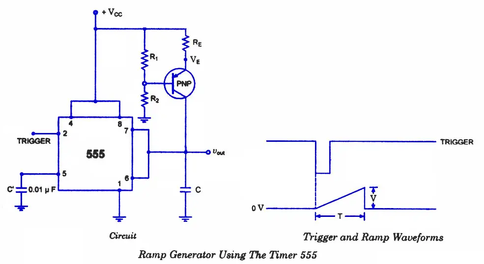
Ramp Generator Circuit
Charging current produced by PNP constant current source is
iC = Vcc-VE / RE
where VE = R2 / (R1 + R2) * VCC + VBE
When a trigger starts the monostable multivibrator timer 555 as shown in figure, the PNP current source forces a constant charging into the capacitor C. The voltage across the capacitor is, therefore, a ramp as illustrated in the figure. The slope of the ramp is given as
Slope, s = I/C
IC Voltage Regulators

Image titled Make a Small Heater Step 1A voltage regulator is one of the most widely used electronic circuitry in any device. A regulated voltage (without fluctuations & noise levels) is very important for the smooth functioning of many digital electronic devices. A common case is with micro controllers, where a smooth regulated input voltage must be supplied for the micro controller to function smoothly.
You may also like this article on Regulated Power Supply
Voltage regulators are of different types. In this article, our interest is only with IC based voltage regulator. An example of IC based voltage regulator available in market is the popular 7805 IC which regulates the output voltage at 5 volts. Now lets come to the basic definition of an IC voltage regulator. It is an integrated circuit whose basic purpose is to regulate the unregulated input voltage (definitely over a predefined range) and provide with a constant, regulated output voltage.
An IC based voltage regulator can be classified in different ways. A common type of classification is 3 terminal voltage regulator and 5 or multi terminal voltage regulator. Another popular way of classifying IC voltage regulators is by identifying them as linear voltage regulator & switching voltage regulator.  There is a third set of classification as 1) Fixed voltage regulators (positive & negative) 2) Adjustable voltage regulators (positive & negative) and finally 3) Switching regulators. In the third classification, fixed & adjustable regulators are basically versions of linear voltage regulators. 

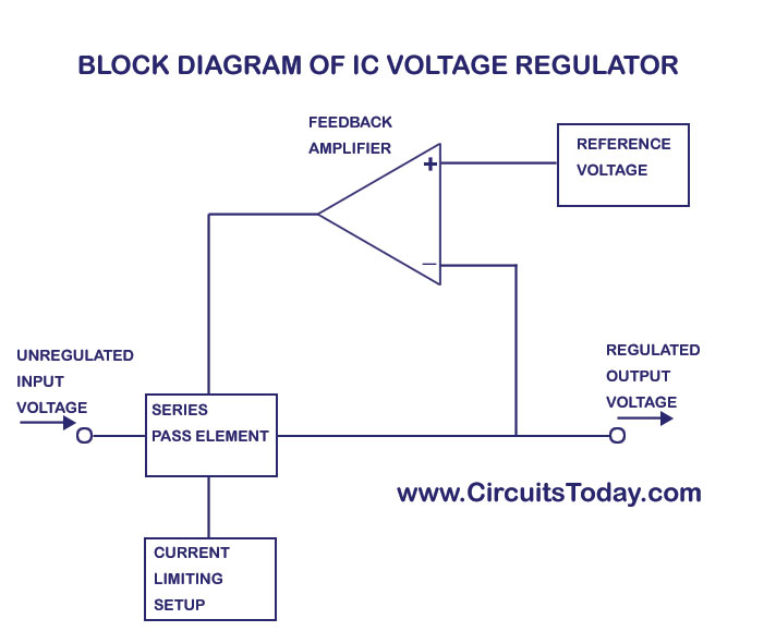
Block Diagram of 3 Terminal IC based Voltage Regulator

We have given below the block diagram of a 3 terminal IC based voltage regulator.
IC Voltage Regulator Block Diagram

3A switching regulator

Description.
When compared to linear voltage regulators the switching voltage regulators are much power efficient. In the case of linear voltage regulators the difference between the input and output voltage is just wasted and for switching regulators there is almost no such wastage and that’s why the switching regulators have great power efficiency ranging up to 85% . In simple words, the switching regulator operates by taking small bits of energy from the input voltage source and then transferring it to the output with the help of a solid state switch and a control circuitry. Since the switching element is either fully open or closed at any moment, no energy is wasted  across it. The control circuit controls  the duty cycle of the solid state switch which in turn determines rate at which energy is transferred to the output.
The electronic circuit given here is of a simple and low cost switching regulator using the IC LM317 that can deliver up to 3A of current. The input voltage range of this circuit is between 8 to 35V DC and the output voltage can be adjusted between 1.8 to 32V DC. The output voltage can be adjusted by using the

Transformerless switch mode power supply circuit

12V/120mA switch mode power supply circuit.

Transformer less switch mode power supplies have become very popular these days. The circuit shown below is of a 12V/120mA output, 85 to 230V AC input transformerless switch mode power supply using LNK304 IC. Applications of a power supply based on this IC includes hand held devices, timers, small appliances, LED drivers, industrial gadgets etc.
LNK304 is a low component count, efficient off-line switcher IC that can support buck, buck-boost and flyback topologies. The IC has a built in auto start circuit for short circuit and open loop fault protection. Other features of LNK304 includes low temperature variation, thermal shut down,high break down voltage, good line & load regulation, high band width , wide input voltage range (85 to 230V AC) etc. In general the LNK304 has a better performance when compared to the many other discrete buck regulators.


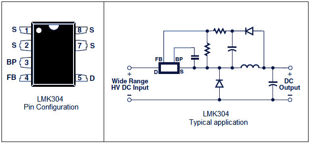
LNK304 pin configuration and typical application
The pin configuration and the typical application diagram of LNK304 are shown above. Drain (D) pin the drain connection of the built in power MOSFET. The external by pass capacitor (0.1uF) is connected to the BYPASS (BP) terminal. FEEDBACK (FB) pin controls the switching of the built in power MOSFET. A current above than 49uA delivered to this pin will inhibit the switching. The internal power MOSFETs source is connected to

10A Adjustable voltage Regulator

10A Adjustable voltage Regulator MSK 5012.

MSK5012 is a highly reliable adjustable voltage regulator.Whose output can be programmed using two resistors. The regulator has a very low dropout voltage(0.45v @10A  )due to the usage of MOSFET with very low Rds (ON) as the internal series pass element.The MS5012 has a high level of accuracy and ripple rejection is around 45dB. It is available in a 5 pin Sip package that is electrically isolated from the internal circuitry. This give us the freedom to fit the IC directly to the heat sink and this sort of direct heat sinking improves the thermal dissipation.

Description.

The output voltage of

Friday, November 27, 2015

Build a 60 Watt Solar Panel

Build a 60 Watt Solar Panel
    Several years ago I bought some remote property in Arizona. I am an astronomer and wanted a place to practice my hobby far away from the terrible light pollution found near cities of any real size. I found a great piece of property. The problem is, it's so remote that there is no electric service available. That's not really a problem. No electricity equals no light pollution. However, it would be nice to have at least a little electricity, since so much of life in the 21st century is dependent on it.

    I built a wind turbine to

    Bicycle Cell Phone Charger (Wind Turbine with build in Battery)

    I go very often to cycle in the nature where is no electricity, and during a long bike tour my phone usually discharges. These smartphones have a large capacity but its consumption is big too. I made a few weeks ago another bike turbine for the Bicycle Contest, but I think I can make a better one. So created an all in one wind turbine power bank.

    I like to combine cycling with electronics (these are my favorite hobbies) so that's why I create so much bike gadgets now for the Bike Contest.

    This project requires basic soldering experience and

    Tuesday, November 10, 2015

    SCR Based SSS Solar Charge Control

    A force-commutated SCR makes a novel Solid State Switch in a solar charge regulator control. Prior art includes relay and transistor switches, but an SCR switch in this type of DC application may be new to the world (normally SCRs are applied in line-commutated AC applications). Advantages include robustness and the requirement of only one conductive device that performs (3) functions: switch, latch and reverse polarity diode (reverse blocking thyristor). The main SCR conducts the charging current from the solar panel to the battery while a 2nd commutation SCR performs the function of commutating (turning off) the main SCR current at the end of the conduction period. All circuitry consists of readily available discrete components. Note that this is old technology and may not be the best or cheapest solar charge control solution, but it makes a great, mind-expanding tech school lab experiment.

    This circuit is applied in fashion similar to

    Secure Power Switch Circuit

    Most of the diagnostic, treatment, and life support devices used in healthcare require regular power supply in order to function properly. Accidentally turning off a medical device can have serious consequences. How can you prevent an accidental or unexpected equipment shutdown?

    Here is a little circuit to prevent such costly disasters. It is nothing but a digital toggle switch with an additional switching protection logic. Here two momentary push button switches (S1 &S2) are used to control the switching of the output load, ie one switch is for normal power swtching & other switch is for enabling the

    3V to 24V Variable Power Supply

    This 3V to 24 volt variable-regulated power supply can be adjusted from 3 to 25 volts and is current limited to 2 amps as shown, but may be increased to 3 amps or more by selecting a smaller current sense resistor (0.3 ohm). The 2N3055 and 2N3053 transistors should be mounted on suitable heat sinks and the current sense resistor should be rated at 3 watts or more.


    Voltage regulation is controlled by 1/2 of a 1558 or 1458 op-amp. The 1458 may be substituted in the circuit below, but it is recommended the supply voltage to pin 8 be limited to 30 VDC, which can be accomplished by adding a 6.2 volt zener or 5.1 K resistor in series with pin 8. The maximum DC supply voltage for the 1458 and 1558 is 36 and 44 respectively. The power transformer should be capable of the desired current while maintaining an input voltage at least 4 volts higher than the desired output, but not exceeding the maximum supply voltage of the op-amp under minimal load conditions.
    The power transformer shown is a center tapped 25.2 volt AC / 2 amp unit that will provide regulated outputs of 24 volts at 0.7 amps, 15 volts at 2 amps, or 6 volts at 3 amps. The 3 amp output is obtained using the center tap of the transformer with the switch in the 18 volt position. All components should be available at Radio Shack with the exception of the 1558 op-amp.

    Variable Power Supply Circuit Diagram

    variable power supply

    Variable Power Supply with 78XX regulator

    This variable power supply is using 7805, 7809, 7812 or 7815 voltage regulators, where the last 2 digits represents the maximum output voltage of the IC.
    This circuit offers excellent ripple rejection, eliminates mains hum, and has a design using a pi filtered C-L-C.

    A core should be chosen to work within the specific frequency as stated by the manufacturer. L1 is a powder core and has 32 turns of 0.75mm wire.

    Variable Power Supply Circuit Diagram

    variable power supply 78xx regulator
    The transformer has a 240V primary and has a secondary rated 24V at 2A. The bridge rectifier contains 4 diodes, their current rating needs to be high with respect to the transformers output current; if not the current may damage the diodes. C1 is the mainfiltering capacitor, the supply is further smoothed by the combination of L1 and C3. C2 and C4 are decoupling capacitors; their action further reduce ripple factor.
    The regulator 78xxr,

    Temperature Controlled DC Fan

    This circuit can cool your heat generating electronic devices by operating a DC fan when the temperature in its vicinity increases above the preset level. Its operation is fully automatic and turns off when the temperature returns normal. It uses a small 12V DC brush less fan used in computers.

    Schematic of DC Fan Controlled by Temperature Circuit

    Fan controlled by temperature circuit
    Note by P Marian: this is an updated version of the old circuit designed by D Mohankumar that didn’t function at

    BENCH POWER SUPPLY


    Here is a regulated power supply for your bench. The 100n capacitors are needed across the input and output of the regulator IC's to prevent high-frequency instability.   The transformer is only 500mA so the maximum you can deliver from the power supply is 300mA TOTAL.


    BATTERY MONITOR

    This circuit makes it possible to monitor the charging process of a battery. After constructing the circuit, final adjustments are simple and the only thing needed is a digital voltmeter for the necessary accuracy. Connect an input voltage of 12.65 volt between the positive and negative connections of the circuit and adjust the VR1 (10K trimmer) until Led 10 lights up. Lower the voltage and in sequence all other LEDs will light up. Check that Led 1 lights up at approximately 11.85 volts. At 12.65 volt and higher the battery is fully charged, and at 11.85 is considered to be at its lowest state. LED 8, 9 and 10 indicate the battery capacity is more than 50%, LED 4 to LED 7 indicate a capacity of 30% - 50% and LED 1 to LED 3 indicate less that 30%. This circuit, with the components shown, uses less than 10mA. Of course you can adapt it to your own needs by making small modifications. This circuit is set for DOT mode, meaning only one LED at a time will be lit. If you wish to use the BAR mode,  connect pin 9 to the positive supply rail, but obviously with increased current consumption. The LED brightness can be adjusted by choosing a different value for the 5k6 resistor connected at pin 6 and 7. The diode 1N4007 was included to protect the circuit from a wrong polarity connection. 

    AUTO CUTOUT

    A 12v relay is connected across the 12v supply. When the output is shorted, the 12v falls to 0v and the relay drops-out. The contacts open the 12v is reapplied to the relay and it will "chatter" if the short is not removed.
    This circuit will simply not work and the relay will simply become a "Buzzer."


    In the following circuit, the transistor will only turn on if the output voltage is above 0.6v.

    AC DETECTOR

    This circuit will detect AC line currents of about 250mA or more without making any electrical connections to the line. Current is detected by passing on of the AC lines through an inductive pickup (L1) made with a 1 inch diameter U-bolt wound with 800 turns of #35 magnet wire. The pickup can be made from other iron type rings or transformer cores that allows enough space to pass one of the AC lines through the center. Only one of the current carrying lines, either the line or the neutral should be put through the center of the pickup to avoid the fields cancelling.
    This is most important is very difficult to achieve. The best method is to make a short extension cord with the three conductors separated from each other.
    If you make a 3-turn loop with say the active line, and pass a straight rod such as a metal bolt, containing 400 or more turns through the centre of the 3-turns, you will produce a very sensitive pick-up.
    The magnetic pickup produces about 4 millivolts for AC line current of 250mA, or AC load of around 30 watts. The signal from the pickup is increased about 200 times at the output of the op-amp pin 7 which is then peak detected by the capacitor and diode connected to pin 7. The second op-amp is used as a comparator which detects a voltage rise greater than the diode drop. The minimum signal
    needed to cause the comparator stage output to switch positive is around 800mV which corresponds to about a 30 watt load on the AC line. The output of the 1458 op-amp will only swing within a couple volts of 
    ground so a voltage divider (1k/470) is used to reduce the no signal voltage to about 0.7 volts. An additional diode is added in series with the transistor base to ensure it turns off when the op-amp voltage is 2 volts. You may get a little bit of relay chatter if the AC load is close to the switching point so a larger load of 50 watts or more is recommended. The sensitivity can be increased by adding more turns to the pickup.

    CONSTANT CURRENT SOURCE

    In the following circuit an LED is used to give a fixed reference voltage to a transistor. The output constant current I out is given by:
    The LED lights up only when a load is connected at the output. Thus it indicates when the circuit is operating.


    The operation of the circuit can be made clearer by re-arranging the components as follows:


    The output will be limited to 100mA by using a red LED and 10R for Re.
    The output will be limited to 500mA by using a red LED and 2R2 for Re.
    The output will be limited to 1A by using a red LED and 1R0 for Re.

    Monday, November 09, 2015

    Thermoelectric Rotational Ornament

    Picture of Thermoelectric Rotational Ornament
    DSC00315.jpg
    DSC00316.jpg
    DSC00287.jpg

    VIDEOS


    Background:
    This is another thermoelectric experiment/ornament where the whole construction (candle, hot side, module and cool side) is rotating and both heating and cooling itself with a perfect balance between module output power, motor torque & rpm, candle efficiency, heat transfer, cooling efficiency, air flow and friction. A lot of physics are going on here but with a very simple construction. I hope you enjoy this project!
    See videos for final result:

    Thermoelectric Generator Project

    Picture of Thermoelectric Generator Project
    The Thermoelectric Generator is an experimental kit which demonstrates the direct conversion of heat into electrical energy using the Seebeck effect.The key component is the Peltier module that will be sandwiched between the two metal cans. As long as there is a substantial temperature differential between the two sides of the Peltier element, sufficient electricity will be generated to power the electric motor to turn the propeller.

    Step 1: Step 1:

    Fire Power: Electricity from heat

    Picture of Fire Power: Electricity from heat
    image.jpg
    image.jpg
    Lego created a robotics contest that focused on the advance of technology in students at schools and other organizations. This contest is known as FLL (First Lego League) and uses Lego's robot kit- Mindstorms. Each year, a theme is chosen to correlate with the robot and the other aspects of the contest. This year's theme is titled "Natures Fury", and it involves natural disasters. A table is set up with "missions" (also made of Legos and relating to natural disasters) that must be completed by a robot built and programmed with

    Arduino Based Auto Transport Device

    AUTO TRANSPORT DEVICE is idea of making a self-driving device that is low cost and can carry high load to its destination. This device is ...