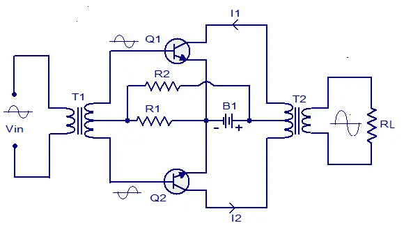
A push pull amplifier is an amplifier
which has an output stage that can drive a current in either direction
through through the load. The output stage of a typical push pull
amplifier consists of of two identical BJTs or MOSFETs one sourcing
current through the load while the other one sinking the current from
the load. Push pull amplifiers are superior over single ended amplifiers
(using a single transistor at the output for driving the load) in terms
of distortion and performance. A single ended amplifier, how well it
may be designed will surely introduce some distortion due to the non
linearity of its dynamic transfer characteristics. Push pull amplifiers
are commonly used in situations where low distortion, high efficiency
and high output power are required. The basic operation of a push pull
amplifier is as follows: The signal to be amplified is first split into
two identical signals 180° out of phase. Generally this splitting is
done using an input coupling transformer. The input coupling transformer
is so arranged that one signal in applied to the input of one
transistor and the other signal is applied to the input of the other
transistor. Advantages of push pull amplifier are low distortion,
absence of magnetic saturation in the coupling transformer core, and
cancellation of power supply ripples which results in the absence of hum
while the disadvantages are the need of two identical transistors and
the requirement of bulky and costly coupling transformers.
Showing posts with label Amplifier. Show all posts
Wednesday, January 20, 2016
Wednesday, January 13, 2016
How To Create Your Signal Jammer
For a long-long time many people
were looking for this cool recipe of making something interesting for yourself.
And I was one of them until last days. In my quest I came across the Jammer Store blog post called How To
Make Your Cell Phone Jammer: DIY Guide. It inspired me to make something like
that by myself.
All necessary info, schemes and pictures are there, so I tried. The result is represented in this humble guide for you.
Tuesday, November 10, 2015
20W FM RF Amplifier Circuit
This FM RF power amplifier has 2 transistors from Philips: BLV10 and BLW87. The 2 rf transistors work in class C and this fm amplifier has a total gain of 21dB (100x) and 55 – 65% efficiency. One low pass filter with 9 components ensures 60dB rejection of the the second harmonic. There is no need for tune-up to cover the whole 88-108 MHz FM band.
20W RF FM amplifier circuit diagram
Source:- http://www.electroschematics.com/18/rf-fm-88-108-mhz-20w-amplifier-blv10-blv87/
FM Radio Receiver
This simple fm radio receiver circuit consists of a regenerative rf stage, TR1, followed by a two of three-stage audio amplifier, TR2 to TR4. In some areas 3 stages of audio amplification may not be necessary, in which case TR3 and its associated components can be omitted and the free end of capacitor C5 connected to the collector of TR2.
Radio Receiver Circuit Diagram
The critical part of the fm radio receiver is the first stage, TR1/VC1, where the wirings must be kept as short as possible. Coil L1 is formed by winding 8 turns of 1mm (20 swg) enamelled copper wire on a 6 mm diameter former, which is then removed. After that L1 should be stretched carefully and evenly to a length of about 13mm.
Transistors List
TR1 = BF199
TR2 = TR3 = TR4 = BC547
TR1 = BF199
TR2 = TR3 = TR4 = BC547
Video presentation and photos of the working radio receiver
The tunning capacitor VC1 is one of the two fm sections of a miniature fm transistor radio with built-in trimmers (VC2). The “earthy” end (moving vanes and spindle) is connected to the 22pF capacitor C1. The value of the rf choke L2 is not critical, anything from 1µH to 10µH being suitable.
The output is suitable for ordinary earphones connected in series to provide an impedance of 64Ω.
Tuning-in the fm radio receiver
To operate the radio receiver, potentiometer VR1 must first be advanced slowly (towards the end of the track connected to battery positive) until, at about the half-way point, a sudden slight increase in background noise will be heard, indicating the onset of oscillation. It then should be backed off, very slowly, until oscillation just stops; it then should be possible to tune in some stations.
The correct frequency range of 87 MHz to 108 MHz can be obtained by adjusting VC2 at the high frequency (108 MHz) and slightly stretching or squeezing together the turns of coil L1 at the end (87 MHz).
Sunday, November 08, 2015
Make your first Serious Amplifier
I did it! I've always wanted to build my own amplifier, and now, finally, I made one. It's my first "serious audio" project ever.
Starting this project was daunting to me. There was a gap between buying the parts and actually making the amplifier... a two year gap, as a matter of fact. I know a thing or two about analog electronics and I can read and understand electronic diagrams, but I never made something from scratch that connects directly to a wall outlet. And I usually make stuff with electronics either for kids or as a "proof of concept", where accuracy and details matter only little. In other words, I was just insecure about me as a maker of Serious Amplifiers.
What helped me to get started is that I just needed an amplifier. I love to play music and the best sound system I had was my iMac. And that proved not good enough for me. So I had the choice between buying a cheap receiver while knowing I had all the parts for a much better amp or just get started building it. Oh boy, I am SO glad I did just that!
If you find yourself dreaming about building an amplifier now and then, but are not sure about how to get it done: Read on! I described the making of my Serious Amp as good as possible, including the mistakes and successes. The result is not a Perfect Amp, but it surely is a Serious One that is not that hard to build even if you never built one before.
--
If you like this project, please vote for it in the contests. Thanks!
--
This amplifier is the best one I've ever owned (that claim isn't worth very much) and I'm really, really happy with it. Even with my secondhand (€10,-) loudspeakers it sounds pretty nice. In the video, the sound is recorded with the on-camera mic. What you hear is far, far away from the real life experience.
The amp is a so called Gainclone, using one LM3886 op-amp per channel. The power supply is based on a (way too large) 230VA toroid transformer. It took me about 32 hours to build the amp and power supply.
In this Instructable, I'll describe how I made the power supply and amplifier. More important, I'll also describe what I would do different if I had to do the project again.
Starting this project was daunting to me. There was a gap between buying the parts and actually making the amplifier... a two year gap, as a matter of fact. I know a thing or two about analog electronics and I can read and understand electronic diagrams, but I never made something from scratch that connects directly to a wall outlet. And I usually make stuff with electronics either for kids or as a "proof of concept", where accuracy and details matter only little. In other words, I was just insecure about me as a maker of Serious Amplifiers.
What helped me to get started is that I just needed an amplifier. I love to play music and the best sound system I had was my iMac. And that proved not good enough for me. So I had the choice between buying a cheap receiver while knowing I had all the parts for a much better amp or just get started building it. Oh boy, I am SO glad I did just that!
If you find yourself dreaming about building an amplifier now and then, but are not sure about how to get it done: Read on! I described the making of my Serious Amp as good as possible, including the mistakes and successes. The result is not a Perfect Amp, but it surely is a Serious One that is not that hard to build even if you never built one before.
--
If you like this project, please vote for it in the contests. Thanks!
--
This amplifier is the best one I've ever owned (that claim isn't worth very much) and I'm really, really happy with it. Even with my secondhand (€10,-) loudspeakers it sounds pretty nice. In the video, the sound is recorded with the on-camera mic. What you hear is far, far away from the real life experience.
The amp is a so called Gainclone, using one LM3886 op-amp per channel. The power supply is based on a (way too large) 230VA toroid transformer. It took me about 32 hours to build the amp and power supply.
In this Instructable, I'll describe how I made the power supply and amplifier. More important, I'll also describe what I would do different if I had to do the project again.
Step 1: Links: Get a grip on the Gainclone Universe
I'm not an audiophile and not an expert on amplifiers either. So when I started to look around on "how to build a Serious Amp", I entered the universe of Gainclone amplifiers. Looking at the sometimes gorgeous designs, I realised I wanted to build one of these babies myself. There are many different ways to build them, so browse around and get yourself familiar with the world of gainclones...
You may have noticed that there are a lot of slightly different schematics and op-amp types that can be used. Not being an expert, I found it hard to make a choice. I turned to a friend who I consider to be an expert for advice. He convinced me just to choose something simple and trustworthy. The differences in the circuits are about details, which are hardly relevant when building your first amp. Novice mistakes will be made and those will have much more impact for the worse than the refined details have for the better.
What I really like about the Gainclone is the minimalistic approach. The general rule with Gainclones is the less components, the better the amp. This comes at a prize, of course: The quality of the components and their specs become more important, since there are so few components to create the sound.
- Mark Hennesy's website: Very, very nice amps and great info on gainclones and powersupplies. Great pics and comments on how he built it. The most inspiring resource I found.
- Wikipedia article on Gainclone amps and where they come from.
- The Chill Amp: Well documented site, including schematics and parts list.
- Chipamp.com: I used their circuit diagram for the amplifier (the pdf is available on their site. Comes along with good tips on building amps). They also sell kits and parts.
- DIY Chip Amps: Nice listing of several DIY gainclone amplifiers.
- Audiosector.com: Stunningly beautiful gainclone amps.
- Decibel Dungeon (that's an audio-nerdy name :-)): Schematics for a gainclone amp and a power supply.
- Decibel Dungeon Gainclone Gallery: Nice collection of DIY gainclone amps.
You may have noticed that there are a lot of slightly different schematics and op-amp types that can be used. Not being an expert, I found it hard to make a choice. I turned to a friend who I consider to be an expert for advice. He convinced me just to choose something simple and trustworthy. The differences in the circuits are about details, which are hardly relevant when building your first amp. Novice mistakes will be made and those will have much more impact for the worse than the refined details have for the better.
What I really like about the Gainclone is the minimalistic approach. The general rule with Gainclones is the less components, the better the amp. This comes at a prize, of course: The quality of the components and their specs become more important, since there are so few components to create the sound.
Step 2: Parts
Depending on your configuration of choice, you need the parts. This is what I have used:
Power Supply:
Amplifier:
Electronics:
Connectors:
Casing:
Anything you like, of course. I used birch plywood, 9 mm thick and alkyd-based clear varnish used foor floors and stairs.
Costs:
All together, I spent around €100,- for the whole project. The toroid transformer is the most expensive part by far: €50,-. The op-amps cost around €9,- each, the big electrolyte capacitors are around €4,-. Please buy a decent potentiometer. I discarded two of these because they caused noise. The one I use now is so-so, for €6,- (which is PEANUTS for a potentiometer in audio, but I'm on a low budget).
Power Supply:
- 1 toroid transformer with double secondary windings: at least 120 VA max output, 2x 12-18 Volt. I used a 230 VA 2x 18 V model, which is really too big for this amp (over 300VA is considered overkill for any amp, so I'm pretty close to that :-))
- 2x 10,000 uF / 35 V electrolytic capacitors
- 1x rectifier module KBU1005
- 1x Anti-interference filter for mains supply: Kemo nr. M41 (I only used it because I had it lying around. I would have left it out otherwise)
- 1x switch. I already had a very nice old model.
- 1x male power plug, Euro model. These plugs are also sold with an integrated power switch, like this one.
- 1x 3 Amp fuse with socket
- 1x 10mm red LED
- 1x 100 kOhm resistor to dim the LED
- about two meters of heavy duty power cable. I used loudspeaker cable for the power cord to the amplifier, and regular power cord for the internal wiring
Amplifier:
Electronics:
- 2x LM3886 op-amps
- 1x 22kOhm potentiometer, logarithmic scale.
- Resistors: 2x 2.7 (2 Watt), 2x 680, 2x 1k, 2x 10k, 4x 22k
- Capacitors electrolytic: 2x 47 uF, 4x 100 uF
- Capacitors film (MKP type): 4x 0.1 uF
- Something that can act as a heatsink for the op-amps. I used a piece of aluminium tube (square profile, 30x30 mm)
Connectors:
- 1 set of RCA "audio-in" connectors. In Dutch, these are called "tulip plugs". I'm not kidding.
- 2 sets of lab connectors to connect the speakers
- 1 set (male and female) 3-way XLR plugs, to connect the power supply to the amp.
- A piece of aluminium to mount the connectors in. I harvested a piece of 150 x 60 x 2 mm aluminium sheet from a discarded PC.
Casing:
Anything you like, of course. I used birch plywood, 9 mm thick and alkyd-based clear varnish used foor floors and stairs.
Costs:
All together, I spent around €100,- for the whole project. The toroid transformer is the most expensive part by far: €50,-. The op-amps cost around €9,- each, the big electrolyte capacitors are around €4,-. Please buy a decent potentiometer. I discarded two of these because they caused noise. The one I use now is so-so, for €6,- (which is PEANUTS for a potentiometer in audio, but I'm on a low budget).
Step 3: Size, footprint and design of the amp
I decided to make separate casings for the power supply and the amp. Thus I can choose to stack the casings or set them side by side.
I made the casings out of wood, because I'm more comfortable with woodworking than with metal. Besides that, I have a thing with clear lacquered birch plywood. I have a bookcase and a dressoir made from it and my daughter sleeps in an ubercool birch plywood bed.
Wood isn't a very sensible choice to make audio-equipment casings from. Most parts that go through the casing (connectors, switch, indicator light, etc.) are designed for mounting in metal cases. 9mm wood is just too thick for most parts to protrude. So for the connectors on the backside of the amplifier casing, I decided to mount them into a separate plate of aluminium, and screw the plate onto the inside of the backside of the casing.
To get a grip on the size of the casing, the size of the power supply is leading (the PS has the largest components by far). I laid out the components on a sheet of paper and found out the whole thing can fit into a rectangle of 148.5 x 210 mm (that's the size of half A4, the document standard in Europe).
The top of the casings is a sheet of perforated aluminium. The sheet I used is 0.8 mm thick, which is a bit too thin: The sheets tend to sag a little. I'm looking out for perfed aluminium sheets of at least 1.5 mm.
I made the casings out of wood, because I'm more comfortable with woodworking than with metal. Besides that, I have a thing with clear lacquered birch plywood. I have a bookcase and a dressoir made from it and my daughter sleeps in an ubercool birch plywood bed.
Wood isn't a very sensible choice to make audio-equipment casings from. Most parts that go through the casing (connectors, switch, indicator light, etc.) are designed for mounting in metal cases. 9mm wood is just too thick for most parts to protrude. So for the connectors on the backside of the amplifier casing, I decided to mount them into a separate plate of aluminium, and screw the plate onto the inside of the backside of the casing.
To get a grip on the size of the casing, the size of the power supply is leading (the PS has the largest components by far). I laid out the components on a sheet of paper and found out the whole thing can fit into a rectangle of 148.5 x 210 mm (that's the size of half A4, the document standard in Europe).
The top of the casings is a sheet of perforated aluminium. The sheet I used is 0.8 mm thick, which is a bit too thin: The sheets tend to sag a little. I'm looking out for perfed aluminium sheets of at least 1.5 mm.
Step 4: Circuit diagrams
These are the circuit diagrams I used. I built them without PCB's, all components of the amp are point-to-point soldered on the chip's leads. For the power supply I used loudspeaker-cable and regular power cord to connect the components.
The secondary coils of the transformator must be connected. To do this right, you must find out which wires to connect. Connecting the wrong leads will result in a 0 Volt output. When connected the right way, you should read 40 to 50 Volts AC. I used an oscilloscope to find the right configuration, but it can also be done with a multimeter, set on AC Voltage.
The rectifier bridge (KBU1005) needs some cooling. I mounted it on a piece of aluminium.
For more info on the circuit: I added some comments with the pictures. Have a look.
The secondary coils of the transformator must be connected. To do this right, you must find out which wires to connect. Connecting the wrong leads will result in a 0 Volt output. When connected the right way, you should read 40 to 50 Volts AC. I used an oscilloscope to find the right configuration, but it can also be done with a multimeter, set on AC Voltage.
The rectifier bridge (KBU1005) needs some cooling. I mounted it on a piece of aluminium.
For more info on the circuit: I added some comments with the pictures. Have a look.
Step 5: Prototype the Power Supply
Not very hard, this step. The power supply has only a few components and is easy to prototype. I connected the parts with connectors and crocodile clamps and hooked it up to an oscilloscope. It worked right away for me.
Step 6: Prototype the amplifier
I found prototyping the amp's difficult. That might have something to do with my choice for point-to-point soldering. Although p2p soldering is not very difficult, it does make the wiring a lot more complicated. I almost had to build one entire channel to be able to test it. If you're reading this: I'd love to have some advice on this...
Here's how the op-amp looks like with the soldered parts:
If I had to make an amplifier again, I would use PCB's instead of the point-to-point soldering. But I never made custom PCB's before, and the op-amp's pins don't fit in the veroboard I normally use.
Repeat this for the second op-amp. But again, my advice is to do this on a PCB if you know how to. I would, however, solder the 22k resistor directly between the op-amp's pins 3 and 9. PCB or not.
Here's how the op-amp looks like with the soldered parts:
If I had to make an amplifier again, I would use PCB's instead of the point-to-point soldering. But I never made custom PCB's before, and the op-amp's pins don't fit in the veroboard I normally use.
- Cut away leads 2, 6 and 11 from the op-amp (picture 1)
- I used a third hand and non-hardening clay to fixate the parts to be soldered.
- Start soldering the parts directly on the pins:
- Solder the 22k resistor from pin 3 to pin 9 in pictures 2 and 3 (it's the feedback path. The connection should be as short as possible). Cut away the protruding leads entirely.
- Solder the 10k resistor between pins 4 and 8 (picture 4). This time, let the resistor protrude from the op-amps chassis. You need the length of the resistor's leads to mount other parts on. Pins 4 and 8 are pretty crowded.
- Solder the 100uF cap's minus side to pin 8 and the 10k resistor (picture 5). Try to make "solder-time" as short as possible. By heating up the resistor it tends to get loose from pin 8.
- Connect pin 7 to the plus-side of the 100uF cap with a piece of bare solid wire (I used jumper wire from a breadboard) (picture 6).
- Solder the 680 Ohm resistor to pin 9. Take care not to un-solder the 22k resistor on pin 9 (pic 7).
- Solder the 47uF cap's minus lead to the plus-side of the 100uF cap. Connect the plus-lead of the 47 uF cap to the 680 Ohm resistor (pic 8).
- Solder a piece of solid kern copper wire to pins 1 and 5 (pic 9). I bent the pins into a small arc so the copper wire wouldn't roll away too easily. Let the wire protrude.
- Finally, solder the wires to +V, -V and ground to resp. pins 1 and 5, pin 4 and pin the plus-side of the 100uF cap (pics 9 and 10).
Repeat this for the second op-amp. But again, my advice is to do this on a PCB if you know how to. I would, however, solder the 22k resistor directly between the op-amp's pins 3 and 9. PCB or not.
Step 7: Volume control, connectors and wiring
Now that you have the amps, it's time to connect power, ground and signal on the plate. I found this the hardest part of the project. That might have something to do with my choice for point-to-point soldering instead of using PCB's. It's wisdom that comes with hindsight, but if I ever make another amplifier I'll use PCB's for sure. The drawing in picture 1 is an attempt to show how I set it up.
I'm not very happy with the result. I'm confident that the wires and connections will not cause shorts, but boy, what a mess! If I ever make another amp, this is the part that I'll want to do better.
Here's how I organised the wiring:
See pics 1 and 5. Grounding: At first, I wanted to ground all components in one place. I read about "ground star-configuration" over here, and it made sense to me. But there's a price to pay: The many wires to the central ground cause a true spaghetti incident in wiring. So after a failure or two, I decided to ground the parts in two different but close spots.
Volume control:
Start easy. See picture 2. The middle lead goes to the amps through a 1k resistor. One other lead goes to ground, the remaining lead must be connected to the input. It's a matter of paying attention and soldering two resistors per channel onto the potentiometer.
Connectors:
I mounted the connectors to an aluminium back plate. The trouble with wiring starts here: All connectors must be grounded, resulting in 6 leads to the "star ground" M4 bolt in the back plate. Try to cut the grounding wires as short as possible. Loopy wires take up space. See pic 3. Start with choosing one of the XLR-plug's pin as ground and connect it to the star ground. Also connect the star ground in the back plate with star-ground 2 on the "floor".
V+ and V-:
See picture 5: I made leads for the V+ and V- connections with solid kern electrical wire. The wires are mounted in 16 amp connectors which are screwed onto the wooden floor. Solder leads from the XLR plug to the V+ and V-.
Write down the XLR's pin numbers that are now connected to Ground, V+ and V-. You will need that when you connect the other side of the XLR plug to the power supply's power cord!
Heat sink:
I glued a piece of alu tube (30x30 mm) over the width of the floor with epoxy. I made some halfway cuts in it to improve ventilation and add some area. The disadvantage of this configuration is that the line-in wires and a ground wire must go through the heat sink. I covered the wires with heat shrink tube to protect them against the heat. Better safe than sorry.
Connect it:
All is ready to be connected now. Connect the potentiometer to the lines-in and ground through the heat sink. Then mount both amps on the heat sink. Start connecting the wires one by one, cutting them as short as possible. Use shrink wrap to isolate the soldered connections where possible. The spaghetti incident is happening right under your hands! With some patience and a decent soldering iron, you'll get there.
I'm not very happy with the result. I'm confident that the wires and connections will not cause shorts, but boy, what a mess! If I ever make another amp, this is the part that I'll want to do better.
Here's how I organised the wiring:
See pics 1 and 5. Grounding: At first, I wanted to ground all components in one place. I read about "ground star-configuration" over here, and it made sense to me. But there's a price to pay: The many wires to the central ground cause a true spaghetti incident in wiring. So after a failure or two, I decided to ground the parts in two different but close spots.
Volume control:
Start easy. See picture 2. The middle lead goes to the amps through a 1k resistor. One other lead goes to ground, the remaining lead must be connected to the input. It's a matter of paying attention and soldering two resistors per channel onto the potentiometer.
Connectors:
I mounted the connectors to an aluminium back plate. The trouble with wiring starts here: All connectors must be grounded, resulting in 6 leads to the "star ground" M4 bolt in the back plate. Try to cut the grounding wires as short as possible. Loopy wires take up space. See pic 3. Start with choosing one of the XLR-plug's pin as ground and connect it to the star ground. Also connect the star ground in the back plate with star-ground 2 on the "floor".
V+ and V-:
See picture 5: I made leads for the V+ and V- connections with solid kern electrical wire. The wires are mounted in 16 amp connectors which are screwed onto the wooden floor. Solder leads from the XLR plug to the V+ and V-.
Write down the XLR's pin numbers that are now connected to Ground, V+ and V-. You will need that when you connect the other side of the XLR plug to the power supply's power cord!
Heat sink:
I glued a piece of alu tube (30x30 mm) over the width of the floor with epoxy. I made some halfway cuts in it to improve ventilation and add some area. The disadvantage of this configuration is that the line-in wires and a ground wire must go through the heat sink. I covered the wires with heat shrink tube to protect them against the heat. Better safe than sorry.
Connect it:
All is ready to be connected now. Connect the potentiometer to the lines-in and ground through the heat sink. Then mount both amps on the heat sink. Start connecting the wires one by one, cutting them as short as possible. Use shrink wrap to isolate the soldered connections where possible. The spaghetti incident is happening right under your hands! With some patience and a decent soldering iron, you'll get there.
Step 8: Build the cases
The wooden cases are fairly easy to make. However, it's easy to mess it up.
I made the cases from 9mm birch plywood. They had three coats of clear lacquer.
I added many pictures of the making of the casings. I think the pics are pretty self-explanatory...
Here are some tips. I learned some of them the hard way...
I made the cases from 9mm birch plywood. They had three coats of clear lacquer.
I added many pictures of the making of the casings. I think the pics are pretty self-explanatory...
Here are some tips. I learned some of them the hard way...
- Use decent tools: Sharp saw and drills, screwdriver that actually fit into screws, etc.
- DON'T RUSH! It will not save you time in the end.
- I remembered just in time to label the panels before sawing them. With the labels on the panels, I could make the grain of the panels continue from one panel into the next when the power supply and the amp are stacked.
- Drill all holes before glueing the panels together.
- I don't have a cutter. I used the table saw to make the groove in the panels for the aluminium sheets. It works well, but the groove is a bit wide (2.5 mm).
- Clamping the panels while maintaining the angles straight is always difficult for me. This time, I made an extra panel with the same size as the bottom and used that as a placeholder for the clamped panels. It worked pretty good.
- Apply the coating in broad daylight! Especially with the second and third layer, it's sometimes hard to see whether parts are missed.
- My first layer of lacquer was too thick. It started dripping after I was finished. It took me careful sanding to get rid of the drips.
Step 9: Fitting the power supply in it's case
Compared to the amplifier, wiring the power supply is a piece of cake! I mounted the parts on a separate wooden floor. The mains plug, the fuse, the switch and the indicator LED are fitted in the case itself.
Browse through the pictures to see what I did. It's not a hard job.
The toroid transformer is mounted on the floor with a 60 mm bolt. I drilled a 20mm hole in the bottom of the case, so that the floor can ly flat on the case's bottom.
In the floor, I drilled two 35mm holes to fit in the big capacitors and I cut away a rectangle to fit the mains filter.
I used a tie-rap around the power cord on the inside of the box as a strain relief. Just in case someone decides to lift the power supply by the power cord...
Browse through the pictures to see what I did. It's not a hard job.
The toroid transformer is mounted on the floor with a 60 mm bolt. I drilled a 20mm hole in the bottom of the case, so that the floor can ly flat on the case's bottom.
In the floor, I drilled two 35mm holes to fit in the big capacitors and I cut away a rectangle to fit the mains filter.
I used a tie-rap around the power cord on the inside of the box as a strain relief. Just in case someone decides to lift the power supply by the power cord...
Step 10: Play it loud!
That's it! As said, my first Serious Amp is the best amplifier I've ever owned and I'm very happy with the result. It's not perfect, though. When the volume is turned up without music playing, a soft noise comes up. It's inaudible when playing music, but it's there. I think it comes from my cheap potentiometer, but a small cap in the line-in might fix it as well. I'm going to have a look at it when I find some time. For now, I totally enjoy playing music. Loud!
Next project: Making a pair of decent loudspeakers :-)
For people reading this who never built an Amp but always wanted to: Just do it! I hope this I'ble gets you the motivation and confidence that you can. If you have questions, write them down in the comments. I'll try to answer them as good as I can.
For people who made Serious Amps before: Please leave your comments and tips for others. It'll be appreciated by me and hopefully a lot of future Amp-builders
Next project: Making a pair of decent loudspeakers :-)
For people reading this who never built an Amp but always wanted to: Just do it! I hope this I'ble gets you the motivation and confidence that you can. If you have questions, write them down in the comments. I'll try to answer them as good as I can.
For people who made Serious Amps before: Please leave your comments and tips for others. It'll be appreciated by me and hopefully a lot of future Amp-builders
Subscribe to:
Posts (Atom)
Arduino Based Auto Transport Device
AUTO TRANSPORT DEVICE is idea of making a self-driving device that is low cost and can carry high load to its destination. This device is ...
-
Here is a more powerful ionisator and ozone generator than described in my version-2. It is meant for continuous operation in problem spac...
-
Need more voltage than your supply can deliver? This is the device to build. Based upon the Vil...
-
AUTO TRANSPORT DEVICE is idea of making a self-driving device that is low cost and can carry high load to its destination. This device is ...