Showing posts with label ic. Show all posts

Wednesday, January 20, 2016

IC Voltage Regulators

Image titled Make a Small Heater Step 1A voltage regulator is one of the most widely used electronic circuitry in any device. A regulated voltage (without fluctuations & noise levels) is very important for the smooth functioning of many digital electronic devices. A common case is with micro controllers, where a smooth regulated input voltage must be supplied for the micro controller to function smoothly.
You may also like this article on Regulated Power Supply
Voltage regulators are of different types. In this article, our interest is only with IC based voltage regulator. An example of IC based voltage regulator available in market is the popular 7805 IC which regulates the output voltage at 5 volts. Now lets come to the basic definition of an IC voltage regulator. It is an integrated circuit whose basic purpose is to regulate the unregulated input voltage (definitely over a predefined range) and provide with a constant, regulated output voltage.
An IC based voltage regulator can be classified in different ways. A common type of classification is 3 terminal voltage regulator and 5 or multi terminal voltage regulator. Another popular way of classifying IC voltage regulators is by identifying them as linear voltage regulator & switching voltage regulator.  There is a third set of classification as 1) Fixed voltage regulators (positive & negative) 2) Adjustable voltage regulators (positive & negative) and finally 3) Switching regulators. In the third classification, fixed & adjustable regulators are basically versions of linear voltage regulators. 

Block Diagram of 3 Terminal IC based Voltage Regulator

We have given below the block diagram of a 3 terminal IC based voltage regulator.
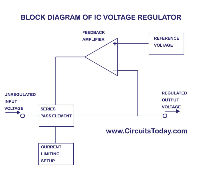
IC Voltage Regulator Block Diagram

Saturday, November 21, 2015

LM1801 Datasheet

LM1801 datasheet specificies that the IC is an extremely low power comparator with a high current, open-collector output stage. The typical supply is only 7µA, yet in its switches state the comparator can source or sink 0.5A. The LM1801 is designed to operate in a standby mode for 1 year, powered by a 9V alkaline battery. Provision is made for operation from supplies of up to 14V.
LM1801 Features
  • 8V to 14V operation
  • direct drive to horn
  • internal zener for supply regulation
  • parallel comparator capability
  • extremely low standby current drain
  • 2 references on chip
  • low battery detector
  • 0.5 output transistor
  • output clamp diodes on chip
LM1801 applications
  • intrusion alarms
  • water leak detectors
  • gas leak detectors
  • overvoltage crowbars
  • battery operated monitors

UM3763 Datasheet

The UM3763 datasheet specifies that this IC is a CMOS LSI circuit which contains analog signal amplifiers and frequency detector for driving motor. It is designed for use in electronic devices and other applications. It is packed with 8 pins DIP.
UM3763 pin configuration

UM3763 features

  • typical 3V operating voltage
  • a motor can be driven by connecting a NPN transistor
  • RC oscillator with one external resistor
  • on-chip analog signal amplifiers
  • use of whistle for controlling
  • the output stage will change when the device senses effective frequency

UM3763 block diagram

UM3763 block diagram

LM1014 Datasheet

LM1014 is a monolithic IC specially designed to provide a low cost motor speed regulator for low voltage DC motors.

LM1014 features
  • 5V to 20V operating voltage range
  • short circuit protection
  • remote pause control
  • saturation voltage 0.1V
  • motor connected to ground for ease of RF suppression
  • motor torque compensation
  • low current consumption

7402 Datasheet

7402 IC is a device containing four independent gates each of which performs the logic NOR function. 7402 package options include: plastic small outline, ceramic chip carriers, flat packages, plastic and ceramic DIPs. The SN7402, SN74LS02 and SN74S02 are characterized for operation from 0°C to 70°C.
7402 connection diagram and function table

MCP1755 Datasheet

The MCP1755/1755S is a family of CMOS low-dropout (LDO) voltage regulators that can deliver up to 300 mA of current while consuming only 68.0 µA of quiescent current (typical). The input operating range is specified from 3.6V to 16.0V, making it an ideal choice for four to six primary cell battery-powered applications, 12V mobile applications and one to three cell Li-Ionpowered applications.
MCP1755 Applications
Battery-powered Devices, Battery-powered Alarm Circuits, Smoke Detectors, CO2 Detectors, Pagers and Cellular Phones, Smart Battery Packs, Portable Digital Assistant (PDA), Digital Cameras, Microcontroller Power, Consumer Products, Battery-powered Data Loggers

LM10 Datasheet

lm10 pinsThe LM10 series are monolithic linear ICs consisting of a precision reference, an adjustable reference buffer and an independent, high quality op amp.

The LM10 IC can operate from a total supply voltage as low as 1.1V or as high as 40V, drawing only 270μA. A complementary output stage swings within 15 mV of the supply terminals or will deliver ±20 mA output current with ±0.4V saturation. Reference output can be as low as 200 mV.

4541 Datasheet

CD4541B programmable timer consists of a 16-stage binary counter, an oscillator that is controlled by external R-C components (2 resistors and a capacitor), an automatic power-on reset circuit, and output control logic. The counter increments on positive-edge clock transitions and can also be reset via the MASTER RESET input.
CD4541B pinout
CD4541B pinout

SMD Code Book and Marking Codes

Here you can download the SMD code book that shows SMD marking codes for almost every surface-mount device available on the market. To identify a particular device, first identify the package style and note the ID code printed on the device.

Next look up the code in the alphanumeric listing which forms the main part of the pdf book by looking for the first character in the left column. You can use the CTRL + F shortcut to search for a certain SMD code because it will be hard to look through 3400 codes, with type numbers, characteristics or equivalents and pinout information.
Preview of the SMD Code Book
smd marking code preview
download the smd codebook

LM567, NE567, SE567 Datasheet

The LM567, NE567 and SE567 are general purpose tone decoders designed to provide a saturated transistor switch to ground when an input signal is present within the passband. The circuit consists of an I and Q detector driven by a voltage controlled oscillator which determines the center frequency of the decoder. External components are used to independently set center frequency, bandwidth and output delay.

567 pin configuration
567 Applications
  • Touch Tone Decoding
  • Precision Oscillator
  • Frequency Monitoring and Control
  • Wide Band FSK Demodulation
  • Ultrasonic Controls
  • Carrier Current Remote Controls
  • Communications Paging Decoders

HT7727A, HT7730A, HT7733A, HT7750A Datasheet

The HT7750A, HT7727A, HT7730A, HT7733A, ICs are a set of PFM step-up DC to DC converters with high efficiency and low ripple. The series feature extremely low start-up voltage and high output voltage accuracy. They require only three external components to provide a fixed output voltage of 2.7V, 3V, 3.3V or 5V.

The HT7727A, HT7730A, HT7733A, HT7750A ICs consist of an oscillator, a PFM control circuit, a driver transistor, a reference voltage unit and a high speed comparator.
pin assignment

ADP1649 1A LED Flash Driver

The ADP1649 is a very compact, highly efficient, single white LED flash driver for high resolution camera phones that improves picture and video quality in low light environments. The LED driver maximizes efficiency over the entire battery voltage range to maximize the input power-to-LED power conversion and to minimize battery current draw during flash events.

ADP1649 applications
  • camera enabled cellular phones and smart phones
  • digital still cameras, camcorders, and PDAs

LED Flash Driver Circuit Schematic

ADP1649 LED Flash Driver

74LS393 Datasheet

Each of these 74LS393 monolithic circuits contains eight masterslave flip-flops and additional gating to implement two individual four-bit counters in a single package. The DM74LS393 comprises two independent four-bit binary counters each having a clear and a clock input. N-bit binary counters can be implemented with each package providing the capability of divide-by-256. The DM74LS393 has parallel outputs from each counter stage so that any submultiple of the input count frequency is available for system-timing signals.
74LS393 pin configuration
74LS393 pin connections
74LS393 features
  • Dual version of the popular DM74LS93
  • DM74LS393 dual 4-bit binary counter with individual clocks
  • Direct clear for each 4-bit counter
  • Dual 4-bit versions can significantly improve system densities by reducing counter package count by 50%
  • Typical maximum count frequency 35 MHz
  • Buffered outputs reduce possibility of collector commutation

L298 Datasheet

The L298 datasheet specifies that the IC is an integrated monolithic circuit in a 15-lead Multiwatt and PowerSO20 packages. It is a high voltage, high current dual full-bridge driver designed to accept standard TTL logic levels and drive inductive loads such as relays, solenoids, DC and stepping motors. Two enable inputs are provided to enable or disable the device independently of the input signals. The emitters of the lower transistors of each bridge are connected together and the corresponding external terminal can be used for the connection of an external sensing resistor. An additional supply input is provided so that the logic works at a lower voltage.
L298 Pin Connection
l298 pin connection
L298 Packages
l298 packages

7404 Datasheet

7404 photoThe 7404 IC contains six independent gates each of which performs the logic INVERT function. The operating voltage is 5V, high-level input voltage is 2V, and low-level input is 0.8V
7404 packages
7404 packages
7404 inverter circuit with 2 LEDs

ULN2003 Datasheet

uln2003 photoThe ULN2003 datasheet specifies that it is a high-voltage high-current Darlington transistor array. Each consists of seven NPN Darlington pairs that feature high-voltage outputs with common-cathode clamp diodes for switching inductive loads. The collector-current rating of a single Darlington pair is 500 mA. The Darlington pairs can be paralleled for higher current capability. Applications include relay drivers, hammer drivers, lamp drivers, display drivers (LED and gas discharge), line drivers, and logic buffers.
ULN2003 package
uln2003 package

HC-SR04 Datasheet

HC-SR04 is an ultrasonic ranging module that provides 2 cm to 400 cm non-contact measurement function. The ranging accuracy can reach to 3mm and effectual angle is < 15°. It can be powered from a 5V power supply.

Sources for downloading HC-SR04 pdf datasheet

HC-SR04 module
HC-SR04 Specifications
  • Working Voltage: DC 5V
  • Working Current: 15mA
  • Working Frequency: 40Hz
  • Max Range: 4m
  • Min Range: 2cm
  • Measuring Angle: 15 degree
  • Trigger Input Signal: 10µS TTL pulse
  • Echo Output Signal Input TTL lever signal and the range in proportion
  • Dimension 45 * 20 * 15mm

7408 Datasheet

7408 IC photo7408 IC is a QUAD 2-Input AND GATES and contains four independent gates each of which performs the logic AND function. Fairchild manufactures this IC in a 14-Lead Plastic Dual-In-Line Package (PDIP), JEDEC MS-001, 0.300″ Wide.
7408 pins and internal diagram

PC817 datasheet

pc817According to PC817 datasheet it contains an IRED optically coupled to a phototransistor. It is packaged in a 4pin DIP, available in wide-lead spacing option and SMT gullwing lead-form option. Input-output isolation voltage(rms) is 5.0kV. Collector-emitter voltage is 80V and CTR is 50% to 600% at input current of 5mA.
PC817 features
  • 4 pin DIP package
  • Double transfer mold package (Ideal for Flow Soldering)
  • High collector-emitter voltage (VCEO:80V)
  • Current transfer ratio (CTR : MIN. 50% at IF=5 mA, VCE=5V)
  • Several CTR ranks available
  • High isolation voltage between input and output (Viso(rms) : 5.0 kV)
  • Lead-free and RoHS directive compliant
PC817 applications
  • I/O isolation for MCUs (Micro Controller Units)
  • Noise suppression in switching circuits
  • Signal transmission between circuits of different potentials and impedances

TL431 Datasheet

TL431 IC
The TL431 is a three-terminal adjustable regulator series with a guaranteed thermal stability over applicable temperature ranges. The output voltage may be set to any value between VREF (approximately 2.5 volts) and 36 volts with two external resistors These devices have a typical dynamic output impedance of 0.2Ω. Active output circuitry provides a very sharp turn-on characteristic, making these devices excel lent replacement for zener diodes in many applications.
TL431 packages
tl431 packages
TL431 features
  • Programmable Output Voltage to 36 Volts
  • Low Dynamic Output Impedance 0.2Ω Typical
  • Sink Current Capability of 1.0 to 100mA
  • Equivalent Full-Range Temperature Coefficient of 50ppm/°C Typical
  • Temperature Compensated For Operation Over Full Rated Operating Temperature Range
  • Low Output Noise Voltage
  • Fast Turn-on Response

Arduino Based Auto Transport Device

AUTO TRANSPORT DEVICE is idea of making a self-driving device that is low cost and can carry high load to its destination. This device is ...