Showing posts with label Sound. Show all posts

Wednesday, January 20, 2016

Puff to OFF LED circuit

Descrption.
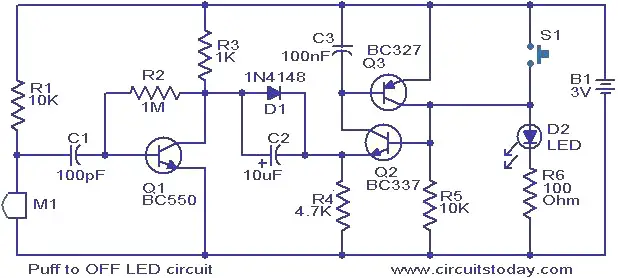
Image titled Make a Small Heater Step 1This is a simple circuit in which the glowing LED can be switched OFF just by a puff. A condenser mic (M1) is used to sense your puff. When the push button S1 is pressed, the transistors Q2 and Q3 wired as latching pair gets activated and drives the LED to glow. The LED remains in this condition. When you puff on the condenser mic, the sound pressure is converted into a voltage signal at its output. This voltage signal will be amplified by the transistor Q1.Since the collector of the Q1 is coupled to the emitter of the latching pair, the pair will stop conducting when ever there is a signal from the condenser mic due to puffing and the LED will go OFF.  The push button switch S1 has to be pressed again to switch the LED ON.
Circuit diagram with Parts list.
puff-top-off-led.JPG
Notes.
  • The circuit can be powered from a 3V battery.
  • The M1 can be a general purpose condenser microphone.
  • The switch S1 can be push button switch.
  • The circuit can be assembled on a good quality PCB or common board.
  • Instead of the LED, you can also try a low power 3V bulb.

Higher Order Filters

Higher Order Filters

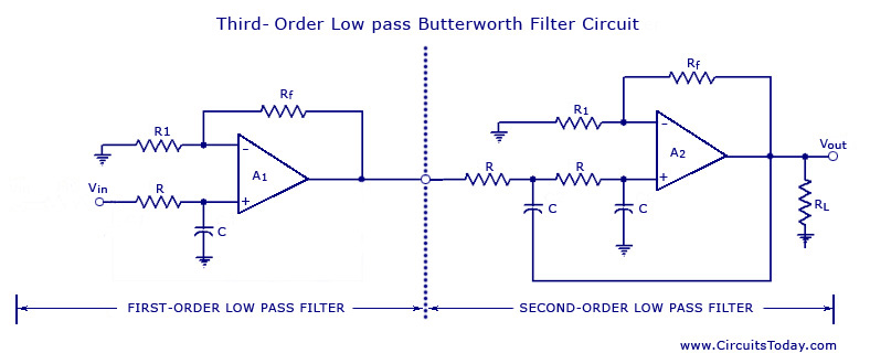
From the discussion made so far on the filters, it may be concluded that in the stopband the gain of the filter changes at the rate of 20 db/decade for first-order filters and 40 db/decade for second-order filters. This means that as the order of the filter is increased, the actual stopband response of the filter approaches its ideal stopband characteristics. In general, a third-order filter produces 60 db/decade, a fourth-order filter produces 80 db/decade and so on.
Higher-order filters, such as third, fourth, fifth, and so on, are built simply by using the first and second-order filters.
The simplest way to build a third-order low-pass filter is by cascading a first order filter with a second-order. Similarly a fourth-order low-pass filter can be formed by cascading two second-order low-pass filters. Although there is no limit to the order of the filter that can be formed, as the order of the filter increases, so does its size. Also the accuracy declines, in that the difference between the actual stopband response and the theoretical stopband re­sponse increases with an increase in the order of the filter.

All pass filters

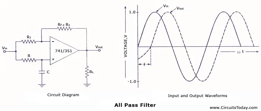
An all-pass filter is that which passes all frequency components of the input signal without attenuation but provides predictable phase shifts for different frequencies of the input signals. The all-pass filters are also called delay equalizers or phase correctors. An all-pass filter with the output lagging behind the input is illustrated in figure.
All pass filter circuit and frequency response

Active and Passive filters

Active and Passive filters – A Comparison:

The simplest approach to building a filter is with passive components (resistors, capacitors, and inductors). In the R-F range it works quite well but with the lower frequencies, inductors create problems. AF inductors are physically larger and heavier, and therefore expensive. For lower frequencies the inductance is to be increased which needs more turns of wire. It adds to the series resistance which degrades the inductor’s performance.
Input and output impedances of passive filters are both a problem, especially below RF. The input impedance is low, that loads the source, and it varies with the frequency. The output impedance is usually relatively high, which restricts the load impedance that the passive filter can drive. There is no isolation between the load impedance and the passive filter. Thus the load will have to be considered as a component of the filter and will have to be taken into consideration while determining filter response or design. Any change in load impedance may significantly alter one or more of the filter response characteristics.

Friday, November 27, 2015

How to Build Custom Speakers


Building your own custom speakers has got to be one of the most rewarding, straightforward and cost-effective DIY activities I've come across. I'm absolutely shocked that it hasn't had a larger presence on Instructables and in the community...well, until now of course.

Some speaker projects can be complete in a weekend, while others can go on for years. Budget speaker kits start around $100, while top-of-the-line kits and components can add up to several thousands of dollars. Regardless of how much you choose to spend on your speakers, you'll likely be building something that will sound as good as commercial product that off the shelf would cost as much as 10 times more.

So, if you've got access to

Tuesday, November 10, 2015

Simple Sound Processor Circuit

Simple Sound Processor presented here is an ultra-simple circuit module suitable for almost all basic electronics and microcontroller projects. For example, this module can be used as a front-end in an electronics project to detect and process ambient sound in an efficient manner. Even less-experienced hobbyists will find the construction of the circuit on a general purpose printed circuit board a fairly easy affair, since there is no perplexed wiring and all components are housed on the board. As the circuit has no critical adjustment points it is immediately ready for real-world applications.
The acoustic sensor in the circuit is a standard omni-directional foil electret microphone (MIC). Sound signals picked up by this microphone is processed by two BC547B transistors (T1 and T2). Pre-processed signals from this section is linked to the monoshot brick realized using the popular NE555N chip (IC1). The whole module can be powered from any standard 5 volt dc supply. Pins 1 and 2 of the 3-pin JST connector (J1) denotes VCC (+5V) and GND (0V) connections respectively, while the final 3rd pin works as the digital signal output (DO) pin.
sound processor circuit
Final component in the circuit – IC2 – is a single chip encapsulated in an SSOP5 package BU4S584G2 which is a single Schmitt trigger inverter, added here to ensure high degree of noise tolerance. However, this is not a critical component, so you can replace it with direct equivalents, if available. Pin description and input/ouput table of BU4S584G2 is shown below:
BU4S584G2
Working of the sound processor circuit is very simple and straight forward. The circuit captures incoming sound signals through the microphone. When the circuit detects a sound activity it generates a digital/logic-level (active-low state) output for a pre- settled duration fixed by the 10K pot (P1). This output can be given to almost all micro controllers for further processing. Although this little circuit module is not intelligent to separate different sounds, it is very useful in making general/microcontroller/robotic projects integrated with sound activation features. As an example, consider the possibility of building a security camera system which takes pictures only when triggered by an audible acoustic wave frequency.
SSP-2
Lab Note:
If you are looking for some other simple solution, you can replace the microphone electronics with a single-transistor circuit as shown below:
mic transistor amp
Prototype tested with both front-end circuits, but a drop-off in sound detection sensitivity was noticed with the second option!

Source:- http://www.electroschematics.com/12327/simple-sound-processor-circuit/

ULTRASONIC REMOTE CONTROL

Here is a low cost, wireless switch controller. It uses ultrasonic sound waves for remote control of a switch.
As with any other remote control, the system basically comprises a transmitter and a receiver circuit. Frequencies up to 20kHz are audible. Frequencies above 20kHz are  not audible. The transmitter circuit generates an ultrasonic frequency between 40-50kHz. The receiver senses the ultrasonic sound and switches on a relay.
The transmitter uses a 555 astable multivibrator. It oscillates at a frequency of 40-50kHz. An ultrasonic transducer is used to transmit the frequency. The transmitter runs on a 9v battery. The ultrasonic receiver uses

ELECTRONIC SIREN

The 741 is a versatile chip and it can be used in the design of a wide variety of sound-effect generators. This circuit produces a siren that can be used in conjunction with other circuits. You can also use an LM358 dual op-amp chip.
The operation of the op-amp was not discussed correctly in the original article, so a full explanation has been provided:

The principle of an op-amp is to provide a very high gain. This means a small change in either input produces an almost full rail swing on the output.
The circuit starts to work like this.
As soon as you put a slight voltage on the "+" input, the output goes full HIGH.
The two 100k resistors on the "+" makes the output go full HIGH.
Now we connect a resistor from the output to "+" and this makes no difference. The output remains full HIGH.
Now we put a resistor from output to "-."
If the "-" input is slightly higher than "+" the output goes LOW. This is what happens. The output voltage drops until the "-" input is slightly lower than the "+" input and that's why the output falls until its voltage is equal to the "+" input.
Now we connect a capacitor to the "-" input.
It does not matter if we add the capacitor later or turn the circuit on with the capacitor fitted.
The voltage on the "-" input will be lower than the "+" input and this will start the circuit oscillating.
This is how it oscillates:
Because the "-" input is lower than the "+" input, the output rises towards the positive rail and this begins to charge the capacitor.
The voltage on the "-" input can rise higher than the "+" input and when it is about 15mV higher, the output drops towards the 0v rail.
This reduces the voltage on the "+"input and the capacitor has to discharge a considerable amount before it is lower than the "+" rail. (Actually before the "+" input is higher than the "-" input).
The voltage on the "+" input is rising and falling by about 30% of rail voltage and this is the amount the capacitor has to charge and discharge for the circuit to work. 


Sunday, November 08, 2015

EL wire color organ

Have you ever used EL wire, or felt that it'd be nice to have a wire that lights up, instead of expensive LED strings?  How about some that pulse with music?  That's what this is for, the EL wire color organ.  EL wire is composed of three wires.  One big center wire surrounded by a phosporous coating.  Two smaller wires are wrapped around it, and connected at the end of the wire.  One end is left open, the other connected to the power supply.  When about 120VAC at a few kHz is run through it, the phosphorous glows.  This is a problem for traditional color organs, as they use either low voltage DC for LEDs, or low frequency AC for incandescent lights.  This project accomplishes the music reaction, high frequency, and high voltage issues with a small device.  I used it for a tron-style holloween costume that reacts to music.

Music LED Light Box

Picture of Music LED Light Box
My original LED light cube got allot of reactions. Some of them where about making the LED's react to music. This did sound very interesting and I found some instructables on here.
Unfortunately I found it very hard to understand those instructables. In my opinion they weren't explained well enough and even some circuits weren't correct.

That's why I though I build one and make an instructable of it. I tried to make this instructable so easy, that everyone with or without any experience can make one!

If you make one, don't forget to share your end result photos and movies with us.

Below you'll see the end result of my Music LED Light Box.

The movie is shot with my Canon Digital Camera, in the dark. My camera can't handle the fast switching between light and dark very well. In reality the effect is even nicer then on the video.


Before people go asking who's music or what songs these are in this video, these beats are made by my brother.  :)
You can visit his website www.motabeatz.com or  YouTube channel for more information and songs.

Headphone Amplifier Circuit Design

Typically, a headphone is connected to the loudspeaker output of the final amplifier stages through a voltage divider circuit. However, this simple design has two distinct disadvantages. Firstly, the headphone volume cannot be varied independently from the main speaker when the main speaker is switched on at the same time. Secondly, the voltage divider circuit causes attenuation at the same time affects the bass output negatively.
The solution to this problem is an independent amplifier for the headphones such as the circuit presented bellow. This headphone amplifier circuit is connected to the output of the final amplifier through the potentiometer P1. IF a stereo headphone is used, this potentiometer must be replaced with a stereo type. Furthermore, the entire circuit must be duplicated for the second channel.
The headphone amplifier delivers an output of around 1 watt. Use a power supply rated at 350 mA. The amplifier gain is dependent of the resistors R4 and R6. The values shown in the circuit gives a gain of 11. The voltage at the junction of R13 and R14 must be set at 50% of the power supply. This can be set through P2. The standby current through the final transistors is about 50 … 110 mA.

Headphone amplifier circuit diagram

headphone amplifier circuit schematic
Typically, a headphone is connected to the loudspeaker output of the final amplifier stages through a voltage divider circuit. However, this simple design has two distinct disadvantages. Firstly, the headphone volume cannot be varied independently from the main speaker when the main speaker is switched on at the same time. Secondly, the voltage divider circuit causes attenuation at the same time affects the bass output negatively.
The solution to this problem is an independent amplifier for the headphones such as the circuit presented bellow. This headphone amplifier circuit is connected to the output of the final amplifier through the potentiometer P1. IF a stereo headphone is used, this potentiometer must be replaced with a stereo type. Furthermore, the entire circuit must be duplicated for the second channel.
The headphone amplifier delivers an output of around 1 watt. Use a power supply rated at 350 mA. The amplifier gain is dependent of the resistors R4 and R6. The values shown in the circuit gives a gain of 11. The voltage at the junction of R13 and R14 must be set at 50% of the power supply. This can be set through P2. The standby current through the final transistors is about 50 … 110 mA.

Sound activated lights circuit

This diy sound activated lights circuit turns a lamp ON for a short duration when the dog barks (or a relatively strong sound) giving an impression that the occupants have been alerted so it can be very useful.
The condenser microphone fitted in a place to monitor sound and generates AC signals, which pass through DC blocking capacitor C1 to the base of transistor BC549 (T1). Transistor T1 along with transistor T2 amplifies the sound signals and provides current pulses from the collector of T2. When sound is produced in front of the condenser mic, triac1 (BT136) fires, activates lights and the bulb (B1) glows for about two minutes.

Schematic of the sound activated lights circuit

sound activated lights circuit schematic
Assemble the circuit on a general purpose PCB (circuit board) and enclose in a plastic cabinet. Power can be derived from a 12V, 500mA step-down transformer with rectifier and smoothing capacitor. Solder the triac ensuring sufficient spacing between the pins to avoid short circuit. Fix the unit in the dog’s cage or close to the sound monitoring spot, with the lamp inside or outside as desired. Connect the microphone to the sount activated lights circuit using a short length of shielded wire. Enclose the microphone in a tube to increase its sensitivity.
Caution: Since the sound activated lights uses 230V AC, many of its points are at AC mains voltage. It could give you lethal shock if you are not careful. So if you don’t know much about working with line voltages, do not attempt to construct this circuit. We will not be responsible for any kind of resulting loss or damage.

Simple Sound Processor

Simple Sound Processor presented here is an ultra-simple circuit module suitable for almost all basic electronics and microcontroller projects. For example, this module can be used as a front-end in an electronics project to detect and process ambient sound in an efficient manner. Even less-experienced hobbyists will find the construction of the circuit on a general purpose printed circuit board a fairly easy affair, since there is no perplexed wiring and all components are housed on the board. As the circuit has no critical adjustment points it is immediately ready for real-world applications.
The acoustic sensor in the circuit is a standard omni-directional foil electret microphone (MIC). Sound signals picked up by this microphone is processed by two BC547B transistors (T1 and T2). Pre-processed signals from this section is linked to the monoshot brick realized using the popular NE555N chip (IC1). The whole module can be powered from any standard 5 volt dc supply. Pins 1 and 2 of the 3-pin JST connector (J1) denotes VCC (+5V) and GND (0V) connections respectively, while the final 3rd pin works as the digital signal output (DO) pin.
sound processor circuit
Final component in the circuit – IC2 – is a single chip encapsulated in an SSOP5 package BU4S584G2 which is a single Schmitt trigger inverter, added here to ensure high degree of noise tolerance. However, this is not a critical component, so you can replace it with direct equivalents, if available. Pin description and input/ouput table of BU4S584G2 is shown below:
BU4S584G2
Working of the sound processor circuit is very simple and straight forward. The circuit captures incoming sound signals through the microphone. When the circuit detects a sound activity it generates a digital/logic-level (active-low state) output for a pre- settled duration fixed by the 10K pot (P1). This output can be given to almost all micro controllers for further processing. Although this little circuit module is not intelligent to separate different sounds, it is very useful in making general/microcontroller/robotic projects integrated with sound activation features. As an example, consider the possibility of building a security camera system which takes pictures only when triggered by an audible acoustic wave frequency.
SSP-2
Lab Note:
If you are looking for some other simple solution, you can replace the microphone electronics with a single-transistor circuit as shown below:
mic transistor amp
Prototype tested with both front-end circuits, but a drop-off in sound detection sensitivity was noticed with the second option!

Arduino Based Auto Transport Device

AUTO TRANSPORT DEVICE is idea of making a self-driving device that is low cost and can carry high load to its destination. This device is ...