Are you familiar with the
basics and applications of the 555 timer IC? Are you looking for a book
that provides all these basics? If so, CircuitsToday has started an
online store from where you can buy books on 555 timer IC, which have
been reviewed in detail. You can go through the reviews and buy them
here:- 3 Great Books to Learn 555 Timer Circuits and Projects
A monostable multivibrator (MMV) often called a one-shot multivibrator, is a pulse generator circuit in which the duration of the pulse is determined by the R-C network,connected externally to the 555 timer.
In such a vibrator, one state of output is stable while the other is
quasi-stable (unstable). For auto-triggering of output from quasi-stable
state to stable state energy is stored by an externally connected
capacitor C to a reference level. The time taken in storage determines
the pulse width. The transition of output from stable state to
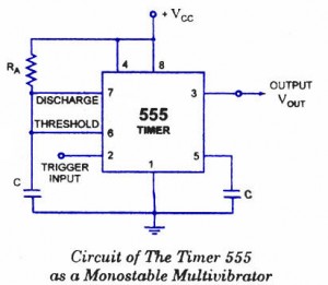
quasi-stable state is accomplished by external triggering. The schematic of a 555 timer in monostable mode of operation is shown in figure.
Monostable Multivibrator Circuit details
Pin 1 is grounded. Trigger input is applied to pin 2. In quiescent condition of output this input is kept at + VCC. To obtain transition of output from stable state to quasi-stable state, a negative-going pulse of narrow width (a width smaller than expected pulse width of output waveform) and amplitude of greater than + 2/3 VCC is applied to pin 2. Output is taken from pin 3. Pin 4 is usually connected to + VCC
to avoid accidental reset. Pin 5 is grounded through a 0.01 u F
capacitor to avoid noise problem. Pin 6 (threshold) is shorted to pin 7.
A resistor RA is connected between pins 6 and 8. At pins 7 a discharge capacitor is connected while pin 8 is connected to supply VCC.
555 IC Monostable Multivibrator Operation.
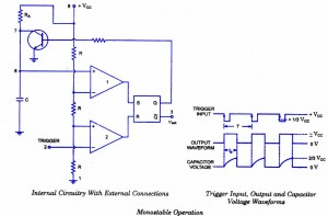
For explaining the operation of timer 555 as a monostable multivibrator, necessary internal circuitry with external connections are shown in figure.
The operation of the circuit is explained below:
Initially, when the output at pin 3 is
low i.e. the circuit is in a stable state, the transistor is on and
capacitor- C is shorted to ground. When a negative pulse is applied to
pin 2, the trigger input falls below +1/3 VCC, the output of
comparator goes high which resets the flip-flop and consequently the
transistor turns off and the output at pin 3 goes high. This is the
transition of the output from stable to quasi-stable state, as shown in
figure. As the discharge transistor is cutoff, the capacitor C begins
charging toward +VCC through resistance RA with a time constant equal to RAC. When the increasing capacitor voltage becomes slightly greater than +2/3 VCC,
the output of comparator 1 goes high, which sets the flip-flop. The
transistor goes to saturation, thereby discharging the capacitor C and
the output of the timer goes low, as illustrated in figure.
Thus the output returns back to stable state from quasi-stable state.
The output of the Monostable
Multivibrator remains low until a trigger pulse is again applied. Then
the cycle repeats. Trigger input, output voltage and capacitor voltage
waveforms are shown in figure.
Monostable Multivibrator Design Using 555 timer IC
The capacitor C has to charge through resistance RA. The larger the time constant RAC, the longer it takes for the capacitor voltage to reach +2/3VCC.
In other words, the RC time constant
controls the width of the output pulse. The time during which the timer
output remains high is given as
tp = 1.0986 RAC
where RA is in ohms and C is in farads. The above relation is derived as below. Voltage across the capacitor at any instant during charging period is given as
where RA is in ohms and C is in farads. The above relation is derived as below. Voltage across the capacitor at any instant during charging period is given as
vc = VCC (1- e-t/RAC)
Substituting vc = 2/3 VCC in above equation we get the time taken by the capacitor to charge from 0 to +2/3VCC.
So +2/3VCC. = VCC. (1 – e–t/RAC) or t – RAC loge 3 = 1.0986 RAC
So pulse width, tP = 1.0986 RAC s 1.1 RAC
The pulse width of the circuit may range
from micro-seconds to many seconds. This circuit is widely used in
industry for many different timing applications.


No comments:
Post a Comment